
Sinter distributed temperature cooling method, sinter time-sharing unloading trolley and distributed temperature unloading device

A cooling method and sinter technology, applied in the field of metallurgy, can solve the problems of increasing the sinter processing capacity of the ring cooler, and achieve the effects of reducing construction costs and operating costs, reducing processing capacity, area and air volume

Active Publication Date: 2016-10-05
ZHONGYE-CHANGTIAN INT ENG CO LTD
View PDF5 Cites 2 Cited by
  • Summary
  • Abstract
  • Description
  • Claims
  • Application Information

AI Technical Summary

Problems solved by technology

[0007] First of all, the temperature of the low-temperature sinter layer is much lower than the unloading temperature of the annular cooler, and there is no need to enter the annular cooler for cooling operations. The traditional cooling process increases the unnecessary sinter processing capacity of the annular cooler

Method used


Image

  • Sinter distributed temperature cooling method, sinter time-sharing unloading trolley and distributed temperature unloading device
  • Sinter distributed temperature cooling method, sinter time-sharing unloading trolley and distributed temperature unloading device
  • Sinter distributed temperature cooling method, sinter time-sharing unloading trolley and distributed temperature unloading device

Examples


Embodiment Construction

[0047] In order to enable those skilled in the art to better understand the solution of the present invention, the present invention will be further described in detail below in conjunction with the accompanying drawings and specific embodiments.

[0048] The sinter temperature fractional cooling method provided by the invention is as follows:

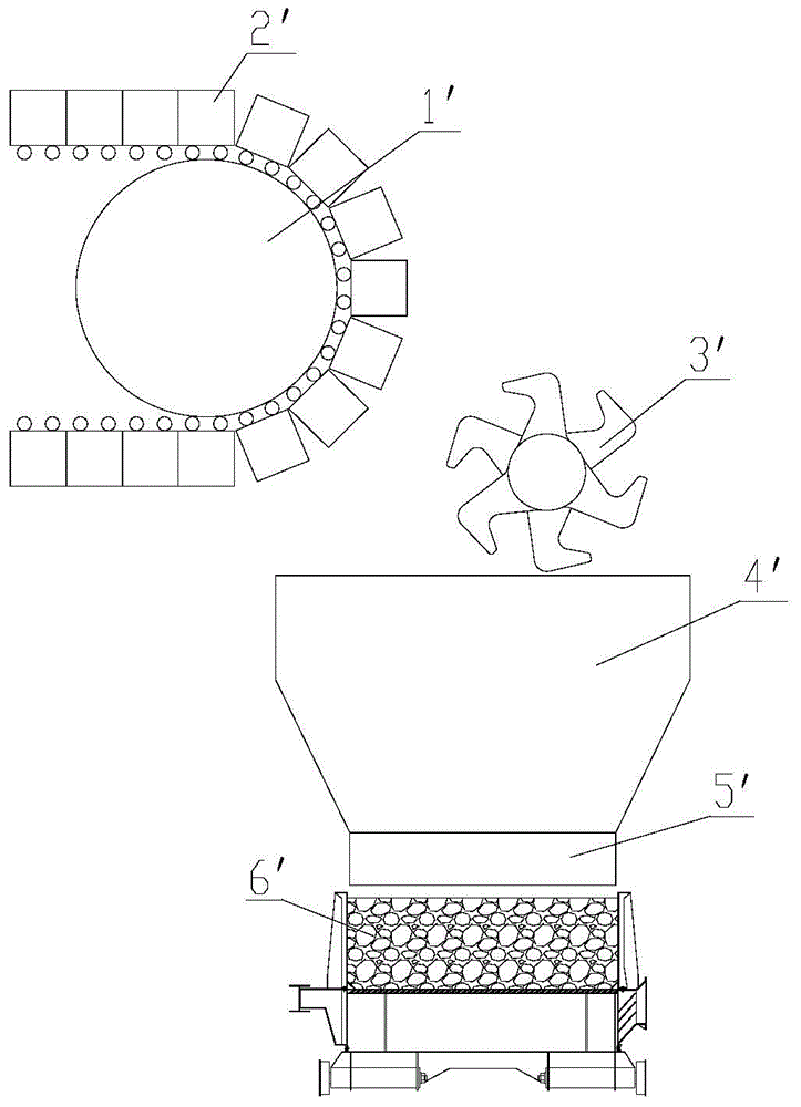
[0049] First, according to the temperature distribution of the sinter layer in the sintering machine trolley, the sinter layer whose temperature is lower than the unloading temperature of the ring cooler is determined as the low-temperature sinter layer, and the rest are determined as the high-temperature sinter layer;

[0050] Then, when unloading at the tail of the sintering machine, time-sharing unloading is carried out to realize the separation of the low-temperature sinter layer and the high-temperature sinter layer. Among them, the low-temperature sinter layer does not enter the ring cooler after being broken, and is directly sent t...


PUM


Abstract

The invention discloses a sinter distributed temperature cooling method. The method comprises the following steps: determining sinter layers with temperatures lower than the unloading temperature of a circular cooler as low temperature sinter layers and determining other sinter layers as high temperature sinter layers according to temperature distribution of sinter layers in a sintering machine trolley at the tail of a sintering machine; and carrying out time-sharing unloading during unloading at the tail of the sintering machine to achieve separation of the low temperature sinter layers and the high temperature sinter layers, wherein the low temperature sinter layers do not enter the circular cooler but are directly conveyed to a follow-up screening procedure after being crushed, and the high temperature sinter layers enter the circular cooler to undergo cooling operation after being crushed. The method has the beneficial effects that the handling capacity of the sinter in the circular cooler can be obviously reduced, the cost of the circular cooler can be reduced and the sinter waste heat recovery can be increased by improving the sinter unloading method and the method of sinter distribution on the circular cooler. The invention also discloses a sinter time-sharing unloading trolley and a distributed temperature unloading device.

Description

technical field [0001] The invention relates to the technical field of metallurgy, in particular to a material distribution method for cooling high-temperature sintered ore in blast furnace ironmaking. The invention also relates to a time-sharing unloading trolley for sintering ore used in the method. Background technique [0002] Sinter is a main raw material for blast furnace ironmaking. High-temperature sintering is iron ore, coke powder and some additives that are fully mixed and evenly arranged on the sintering machine. The ignition furnace ignites the upper surface of the material layer. Burn down until the bottom of the bed. [0003] During the sintering process of the material layer, the combustion-supporting air required for the combustion of the lower material layer must pass through the sintered upper layer of material layer, where the combustion-supporting air is usually normal temperature air, which will be cooled during the process of passing through the sint...

Claims


Application Information

Patent Timeline
IPC IPC(8): F27D15/02F27D3/00
Inventor 田万一王建平
Owner ZHONGYE-CHANGTIAN INT ENG CO LTD
Learn More