
Vision sensing-based laser-electric arc hybrid welding real-time automatic control device and welding method thereof

An automatic control device and hybrid welding technology, applied in laser welding equipment, welding equipment, manufacturing tools, etc., can solve the problem that the distance between the droplet and the center of the laser keyhole is too far, the adjustment process cannot be visualized, and the center of the droplet and the laser keyhole The distance cannot be adjusted in real time to achieve the effect of improving stability and avoiding reflective effects

Active Publication Date: 2016-10-12
CHANGCHUN UNIV OF SCI & TECH
View PDF8 Cites 24 Cited by
  • Summary
  • Abstract
  • Description
  • Claims
  • Application Information

AI Technical Summary

Problems solved by technology

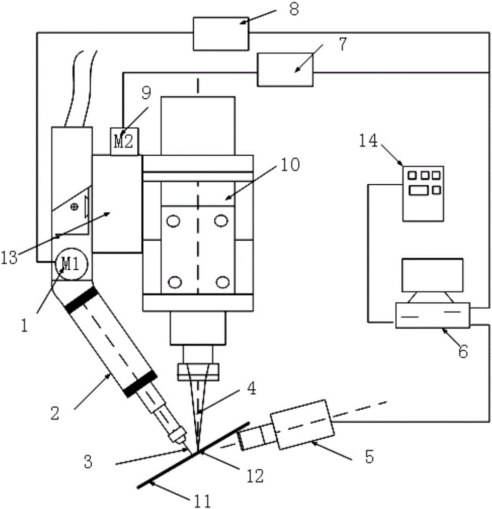
[0006] In order to achieve the above purpose, the present invention proposes a real-time automatic control device for laser-arc hybrid welding based on visual sensing, which improves the stability of the welding process, improves the performance of weld formation and joints, and solves the problems in the prior art. The center distance between the droplet and the laser keyhole cannot be adjusted in real time, and the adjustment process cannot be visualized, resulting in the problem that the center distance between the droplet and the laser keyhole is too far or too close

Method used


Image

  • Vision sensing-based laser-electric arc hybrid welding real-time automatic control device and welding method thereof
  • Vision sensing-based laser-electric arc hybrid welding real-time automatic control device and welding method thereof
  • Vision sensing-based laser-electric arc hybrid welding real-time automatic control device and welding method thereof

Examples


Embodiment 1

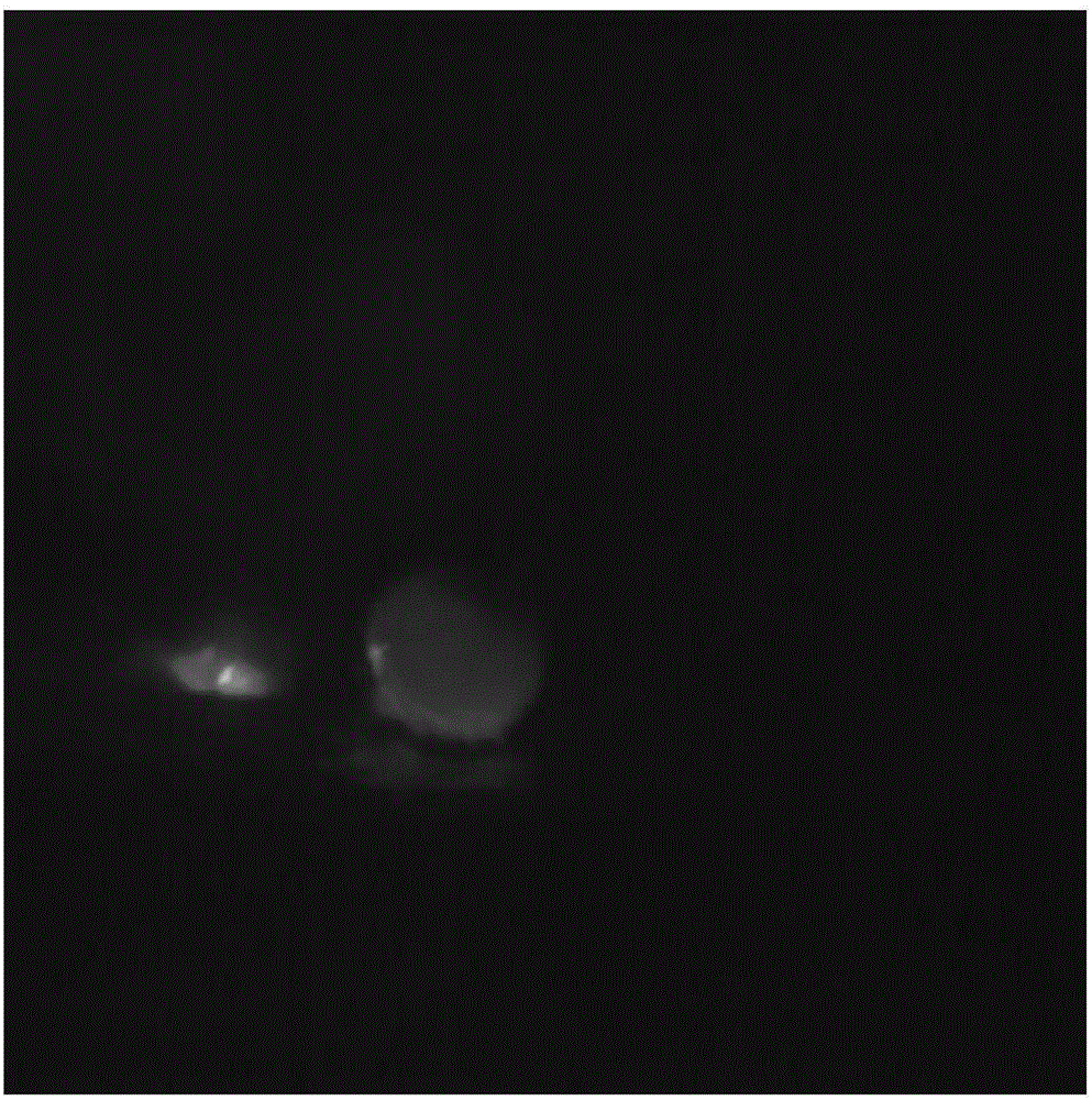
[0049] Adopt the welding method of laser-arc hybrid welding real-time automatic control device of the present invention, as Figure 4-5 As shown, follow the steps below:

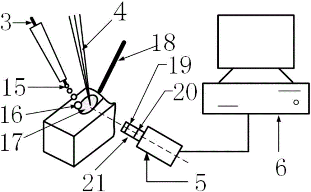
[0050] Step 1: Before welding, clamp the weldment 11 with a thickness of 8.0mm on the workbench. The laser adopts Nd:YAG solid-state laser from Trumpf, Germany. The laser is focused by a 220mm focusing lens to obtain a 0.5mm diameter spot; defocus The power of the Nd:YAG solid-state laser is 2.0KW; the welding torch 2 uses a Panasonic YD-350AG2HGE MIG welding torch with a maximum arc current of 350A. The length is 14mm, the relative welding speed of welding torch 2 is 800mm / min, the diameter of welding wire of welding torch 2 is Φ1.2mm, and the shielding gas of welding torch 2 is CO with a volume ratio of 5%. 2 The %Ar of +95, the gas flow rate is 15L / min; Set the parameter of high-speed camera 5, under the condition that does not have optical filter 19, the aperture 20 of lens 21 is adjusted to 4, exposure...

Embodiment 2

[0056] Adopt the welding method of laser-arc hybrid welding real-time automatic control device of the present invention, as Figure 4-5 As shown, follow the steps below:

[0057] Step 1: Before welding, clamp the weldment 11 with a thickness of 8.0mm on the workbench, and the laser uses CO 2 Laser with a power of 2.0KW; Welding torch 2 adopts Panasonic YD-350AG2HGE MAG welding torch with a maximum arc current of 350A, adjust the arc welding current of welding torch 2 to 200A, arc voltage to 27V, dry elongation of welding wire to 14mm, and the relative welding speed of welding torch 2 800mm / min, the welding wire diameter of welding torch 2 is Φ1.2mm, and the shielding gas of welding torch 2 is CO with a volume ratio of 5%. 2 The %Ar of +95, the gas flow rate is 17L / min; Set the parameter of high-speed camera 5, under the condition that does not have optical filter 19, the aperture 20 of lens 21 is adjusted to 6, exposure time is adjusted to 1 / 50, sampling frequency Adjust to ...

Embodiment 3

[0063] Adopt the welding method of laser-arc hybrid welding real-time automatic control device of the present invention, as Figure 4-5 As shown, follow the steps below:

[0064] Step 1: Before welding, clamp the weldment 11 with a thickness of 8.0mm on the workbench, and the laser uses CO 2 Laser with a power of 2.0KW; welding torch 2 adopts Panasonic YD-350AG2HGE MAG welding torch with a maximum arc current of 350A, adjust the arc welding current of welding torch 2 to 200A, arc voltage to 26V, dry elongation of welding wire to 14mm, and the relative welding speed of welding torch 2 800mm / min, the welding wire diameter of welding torch 2 is Φ1.2mm, and the shielding gas of welding torch 2 is CO with a volume ratio of 5%. 2 The %Ar of +95, the gas flow rate is 16L / min; Set the parameter of high-speed camera 5, under the condition without filter 19, the aperture 20 of lens 21 is adjusted to 6, exposure time is adjusted to 1 / 50s, sampling frequency Adjust to 50 frames per seco...


PUM

PropertyMeasurementUnit
lengthaaaaaaaaaa

Abstract

The invention discloses a vision sensing-based laser-electric arc hybrid welding real-time automatic control device and a welding method thereof. A welding gun is connected with a laser head. The fused welding wire tip of a welding wire forms a molten drop in the welding process. A laser beam is irradiated to weldment, and a laser keyhole is formed. A high-speed camera is used for filming images of the fused welding wire tip and the laser keyhole. The high-speed camera is connected with an image processing industrial personal computer. The image processing industrial personal computer is connected with a combined welding head control device of the welding gun and a welding equipment control device of the welding gun. The image processing industrial personal computer controls the distance between the central point of the laser keyhole and the central point of the molten drop through the combined welding head control device of the welding gun and controls the vertical coordinate Y value of the central point of the fused welding wire tip through the welding equipment control device of the welding gun. By the adoption of the vision sensing-based laser-electric arc hybrid welding real-time automatic control device and the welding method thereof, the problems that in the prior art, the distance between the center of a molten drop and the center of a laser keyhole cannot be adjusted in real time, visualization of the adjusting process cannot be achieved, and accordingly the distance between the center of the molten drop and the center of the laser keyhole is too large or too small are solved.

Description

technical field [0001] The invention belongs to the field of welding technology, and relates to a real-time automatic control device for laser-arc composite welding based on visual sensing and a welding method thereof. Background technique [0002] The development of modern production and science and technology has higher and higher requirements for automation technology, and the automation of welding technology is also the future development trend. Laser arc-hybrid welding has been widely researched and applied due to its advantages of high bridging, high welding speed, large penetration and low cost. There are many controllable factors in this welding method, and the change of any one of them will have a great impact on the welding quality, especially the relative position of the droplet dripping position and the laser keyhole is particularly important. A large number of studies have found that when the dripping position is far away from the laser keyhole (that is, the di...

Claims


Application Information

Patent Timeline
Patent Type & Authority Applications(China)
IPC IPC(8): B23K26/348B23K26/035
CPCB23K26/035B23K26/348
Inventor 刘双宇李彦清张宏刘凤德刘佳石岩徐春鹰黄根哲
Owner CHANGCHUN UNIV OF SCI & TECH
Learn More