Flow control device and method

A flow control device and flow control technology, which is applied in jet propulsion devices, rocket engine devices, machines/engines, etc., can solve the problems of inability to achieve long-life service requirements, poor part consistency, thruster failure, etc., and achieve inhibition of solubility The effect of impurity deposition, inhibition of heat evaporation, and improvement of the life of the whole machine

Active Publication Date: 2016-10-12
BEIJING INST OF CONTROL ENG
View PDF5 Cites 8 Cited by
  • Summary
  • Abstract
  • Description
  • Claims
  • Application Information

AI Technical Summary

Problems solved by technology

[0004] (1) To achieve a small propellant mass flow rate (tens of milligrams per second of liquid propellant) through several uniformly arranged injection microholes, the diameter of each injection microhole will be small, which is difficult to process, and the parts poor consistency
[0005] (2) Small-diameter micropores are prone to clogging caused by residual soluble impurities produced by the volatilization of liquid propellants at high temperatures during long-term high-temperature ignition, and fragmentation residues produced by catalyst particles in the chemical reaction process, resulting in thruster failure, unable to achieve long-life requirements

Method used


Image

  • Flow control device and method
  • Flow control device and method

Examples


Embodiment

[0045] Implementation steps of the present invention are as follows:

[0046] Thruster Quantitative Parameters: Propellant Quota Injection Pressure: 1.7MPa

[0047] Rated flow of propellant: 50mg / s

[0048] Catalytic bed design fuel pressure: 0.5MPa

[0049] Thruster rated thrust: 100mN

[0050] Thruster steady state ignition life: 500 hours

[0051] The implementation steps are as follows:

[0052] 1. The upstream propellant injection pressure of the flow control damping component is 1.7MPa. Select a combined fluid control damping component with a large effective flow area, and try to avoid using a single-hole fluid damping component to improve the overall anti-pollution ability of the thruster.

[0053] 2. Select a solenoid valve with strong flow capacity. The solenoid valve only controls the on-off of the propellant flow process during the flow control process, and does not participate in the flow pressure adjustment process.

[0054] 3. The propellant flows through th...


PUM


Abstract

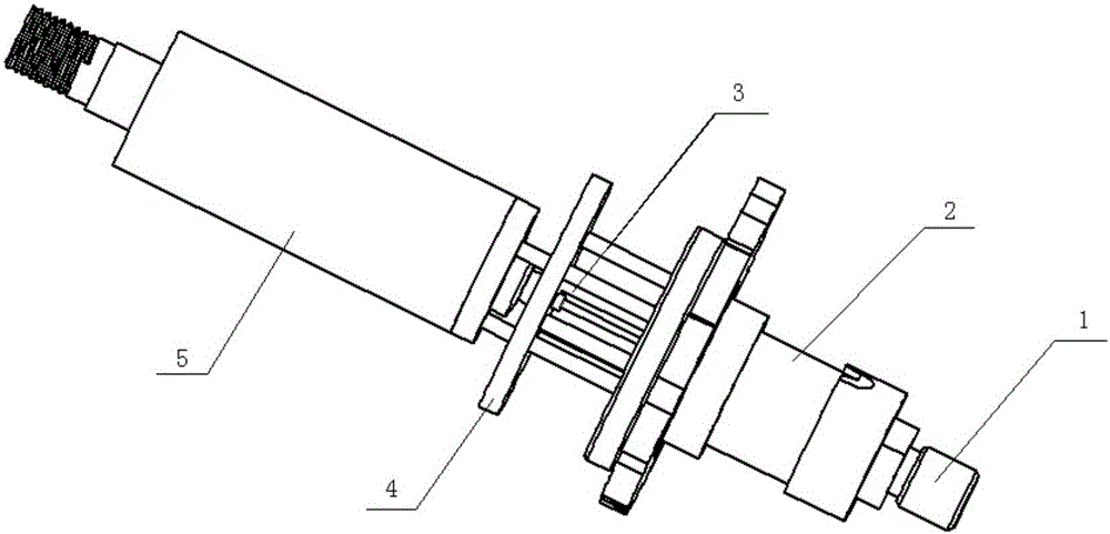
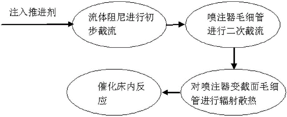
The invention discloses a flow control device and method. The flow control device comprises a fluid damper, an electromagnetic valve, an inspirator, a radiation fin and a catalytic bed. A fluid channel used for conducting throttling on a propellant is formed in the fluid damper. The fluid damper is connected with an inlet in one end of the electromagnetic valve. A propellant passageway is formed in the electromagnetic valve. The propellant passageway communicates with the fluid channel. The internal diameter of the propellant passageway in the electromagnetic valve is larger than that of the fluid channel in the fluid damper. The electromagnetic valve is connected with the catalytic bed through the inspirator. According to variable-section capillary tubes of the inspirator of the flow control device, by increasing the flow area of the root portions of the capillary tubes, the contamination resistance of the capillary tubes is improved, and the service life of a whole thruster is prolonged. Compared with an existing flow control device with the service life shorter than 50 hours, the service life of the flow control device can be prolonged to 500-1000 hours.

Description

technical field [0001] The invention relates to a flow control device and method, belonging to the field of thrusters. Background technique [0002] The single-component thruster uses anhydrous hydrazine as a liquid propellant. When the thruster is working, the chemical energy is converted into internal energy through the catalytic decomposition reaction of anhydrous hydrazine in the catalytic bed to form high-temperature and high-pressure gas, which works through the nozzle. Generate thrust. At present, the working life of a typical small flow (10mg / s-200mg / s mass flow) monolithic thruster is about tens of hours. One of the important factors restricting the service life is that conventional monopropellant thrusters generally use the capillary in the injector or the small holes on the injection panel of the injector to realize the flow control of the propellant. To achieve small propellant flow rates, the inner diameter of the capillary or the diameter of the small hole on...

Claims


Application Information

Patent Timeline
Patent Type & Authority Applications(China)
IPC IPC(8): F02K9/52F02K9/58
CPCF02K9/52F02K9/58
Inventor 姚兆普陈君张伟武胜勇杨春雷吴耀武李胜军
Owner BEIJING INST OF CONTROL ENG
Why Eureka
Try Eureka