Waste incineration boiler device

A boiler device and waste incineration technology, applied in the direction of incinerators, combustion methods, combustion types, etc., can solve problems such as the gap in comprehensive utilization, and achieve the effect of high resource recovery and reuse rate

Inactive Publication Date: 2016-10-12
HARBIN JINJING BOILER
View PDF0 Cites 12 Cited by
  • Summary
  • Abstract
  • Description
  • Claims
  • Application Information

AI Technical Summary

Problems solved by technology

But practice has proved that its disadvantages are also obvious: first, the investment is large and the operating cost is high; second, incineration has certain requirements on the calorific value of waste, and combustion-supporting fuel must be mixed; third, the treatment of waste gas from incineration is difficult and expensive. Im

Method used


Image

  • Waste incineration boiler device

Examples


Embodiment 1

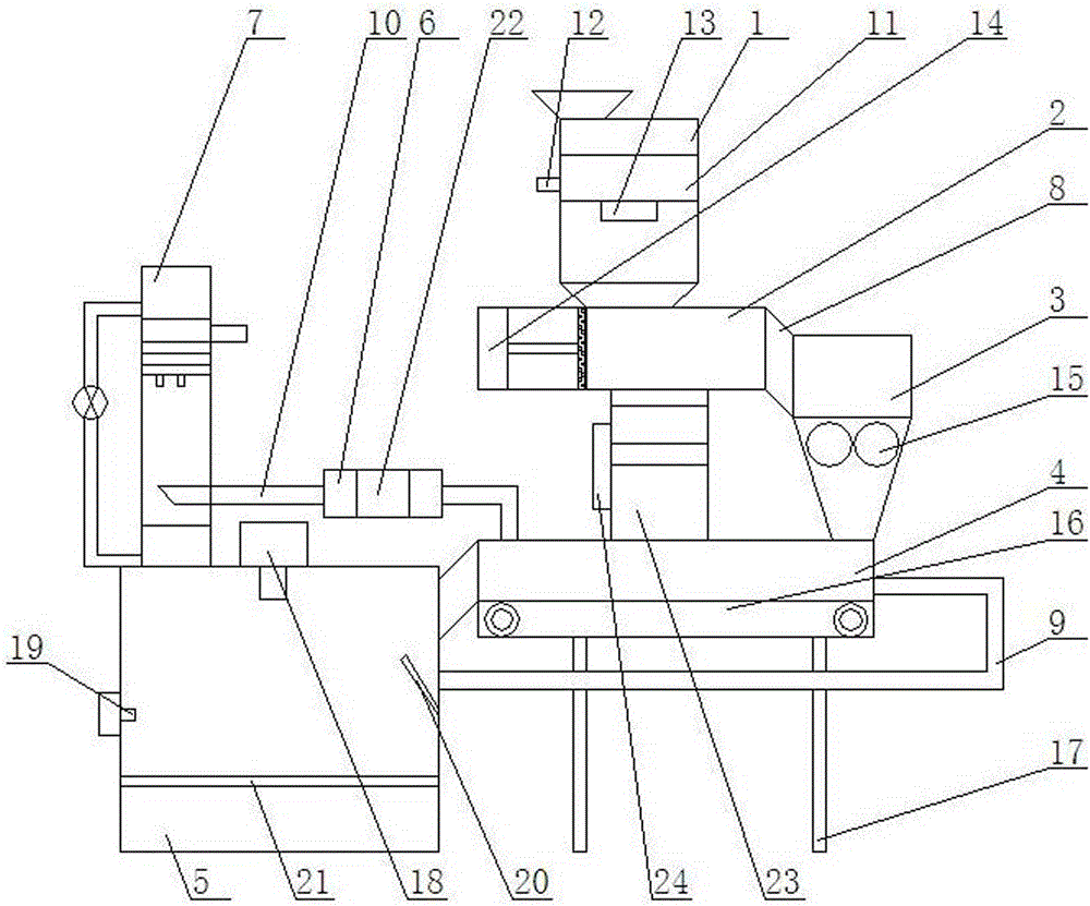
[0026] like figure 1 As shown, a waste incineration boiler device includes a recovery chamber 1, a compression chamber 2, a crushing chamber 3, a drying chamber 4, an incineration power generation chamber 5, a flue gas filtration chamber 6, and a spray treatment chamber 7. The recovery chamber 1 The device is at the top of the compression chamber 2, the compression chamber 2 is connected to the crushing chamber 3 through the inclined conveying pipe 8, the crushing chamber 3 is installed at the upper right end of the drying chamber 4, and the drying chamber 4 is connected to the incineration power generation through the inclined conveying pipe 8 chamber 5, the middle end of the right side of the incineration power generation chamber 5 is connected to the middle end of the right side of the drying chamber 4 through the flue gas pipe 9, and the left side of the top of the drying chamber 4 is connected to the flue gas filter chamber 6 through the flue gas pipe 9, so The flue ga...

Embodiment 2

[0028] like figure 1 As shown, the top of the recovery chamber 1 is equipped with a garbage drop-in opening, and the interior is equipped with a magnetic separation device 11, and the magnetic separation device 11 has a recovery port 12 and a non-recovery port 13.

Embodiment 3

[0030] Such as figure 1 As shown, the hydraulic compression device 14 is installed inside the compression chamber 2, which is composed of a hydraulic drive device, a hydraulic rod, and a compression push plate. The hydraulic drive device is connected to the hydraulic rod, and the hydraulic rod is connected to the compression push plate.


PUM


Abstract

A waste incineration boiler device comprises a recycling chamber, a compressing chamber, a pulverizing chamber, a drying chamber, an incineration generator chamber, a smoke filtering chamber and a sprinkling treatment chamber, wherein the recycling chamber is arranged at the top end of the compressing chamber, the compressing chamber is connected with the pulverizing chamber through an oblique conveying pipe, the pulverizing chamber is arranged at the right upper end of the drying chamber, the drying chamber is connected with the incineration generator chamber through an oblique conveying pipe, the middle end of the right side of the incineration generator chamber is connected with the middle end of the right side of the drying chamber through a smoke pipe, the left side of the top end of the drying chamber is connected with the smoke filtering chamber through a smoke pipe, and the smoke filtering chamber is connected with the sprinkling treatment chamber through an exhaust pipe. The waste incineration boiler device adopts an efficient and environment-friendly method to treat living wastes, and heat produced in the treatment process can be converted to electricity to be utilized. The waste incineration boiler device has the advantages of being high in efficiency, saving in energy, high in resource recycling and reutilizing rate, friendly to environment and free of pollution.

Description

Technical field [0001] The invention involves the field of garbage treatment technology, especially a waste incineration boiler device. Background technique [0002] With the development of the economy, the problem of environmental pollution is also serious.Since cities are generally local political and economic centers, environmental pollution is the most serious.This environmental pollution is all -round, including air pollution, water pollution, soil pollution, etc.; The source of pollution substances is also comprehensive, including exhaust gas, waste water and waste residue. Among them, urban waste is a major source of waste residue pollution. [0003] At present, according to incomplete statistics, my country's garbage dumps have invaded more than 750,000 acres, and their annual economic losses are as high as hundreds of millions of yuan.For example, the urban domestic waste exceeds 200 million tons per year by making 440 kg of garbage per person.The existing garbage treatm...

Claims


Application Information

Patent Timeline
IPC IPC(8): F23G5/033F23G5/04F23G5/46F22B1/18F23J15/02F23J15/04
CPCY02E20/12F23G5/033F22B1/18F23G5/04F23G5/46F23G2201/10F23G2201/80F23G2206/10F23G2206/203F23J15/025F23J15/04F23J2217/10F23J2217/50
Inventor 谷哲学
Owner HARBIN JINJING BOILER
Why Eureka
Try Eureka