Manufacturing method of R-T-B sintered magnet

A technology of R-T-B and sintered magnets, which is applied in the manufacture of inductors/transformers/magnets, electrical components, circuits, etc., which can solve problems such as inability to use multiple times, labor-intensive manufacturing, etc., and achieve the effect of suppressing cracking

Active Publication Date: 2016-10-12
HITACHI METALS LTD
View PDF9 Cites 6 Cited by
  • Summary
  • Abstract
  • Description
  • Claims
  • Application Information

AI Technical Summary

Problems solved by technology

Therefore, the Dy and Tb iron alloy powders disclosed in Patent Document 3 must be completely removed from the furnace every time they are heat treated, and the Dy and Tb iron alloy powders cannot be used many times.
In addition, since the process of dissolving the iron alloy powder of Dy and Tb in a solvent and applying it or coating it in the form of a slurry is added, there is a problem that the production of the R-T-B type sintered magnet is labor-intensive.

Method used


Image

  • Manufacturing method of R-T-B sintered magnet
  • Manufacturing method of R-T-B sintered magnet
  • Manufacturing method of R-T-B sintered magnet

Examples


experiment example 1

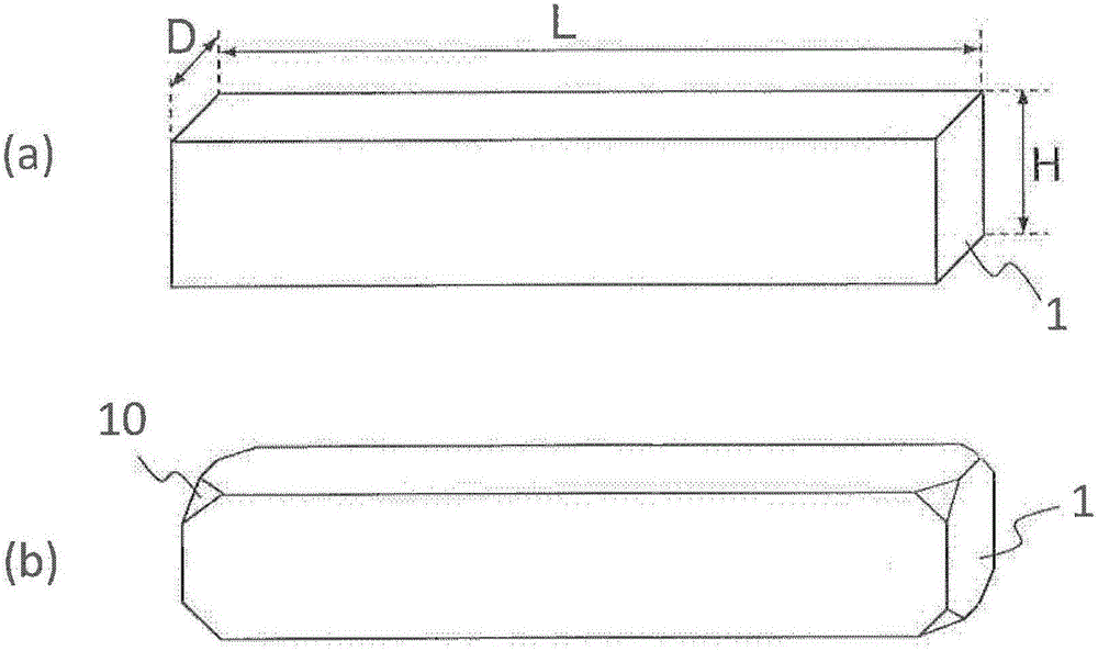
[0111] First, an R-T-B type sintered magnet with a composition ratio of Nd=22.5, Pr=7.0, Dy=0.6, B=1.0, Co=2.0, Al=0.2, Cu=0.1, Ga=0.1, and remainder=Fe (mass %) was produced. Raw material (magnet raw material P). By machining it, a cuboid R-T-B type sintered magnet raw material of 60 mm×4 mm×7 mm elongated in one direction was obtained. After that, chamfers were formed on the eight vertices of the sintered magnet raw material. The magnetic properties of the prepared R-T-B type sintered magnet raw materials were measured by a B-H tracer. As a result, the coercivity H in the properties after heat treatment (500°C) cJ 1100kA / m, residual magnetic flux density B r It is 1.42T.

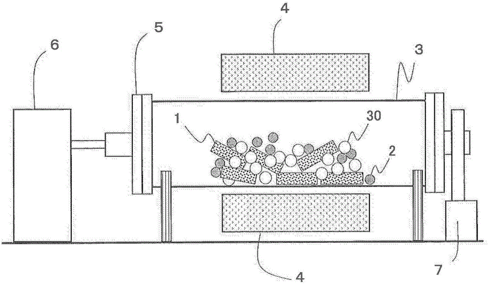
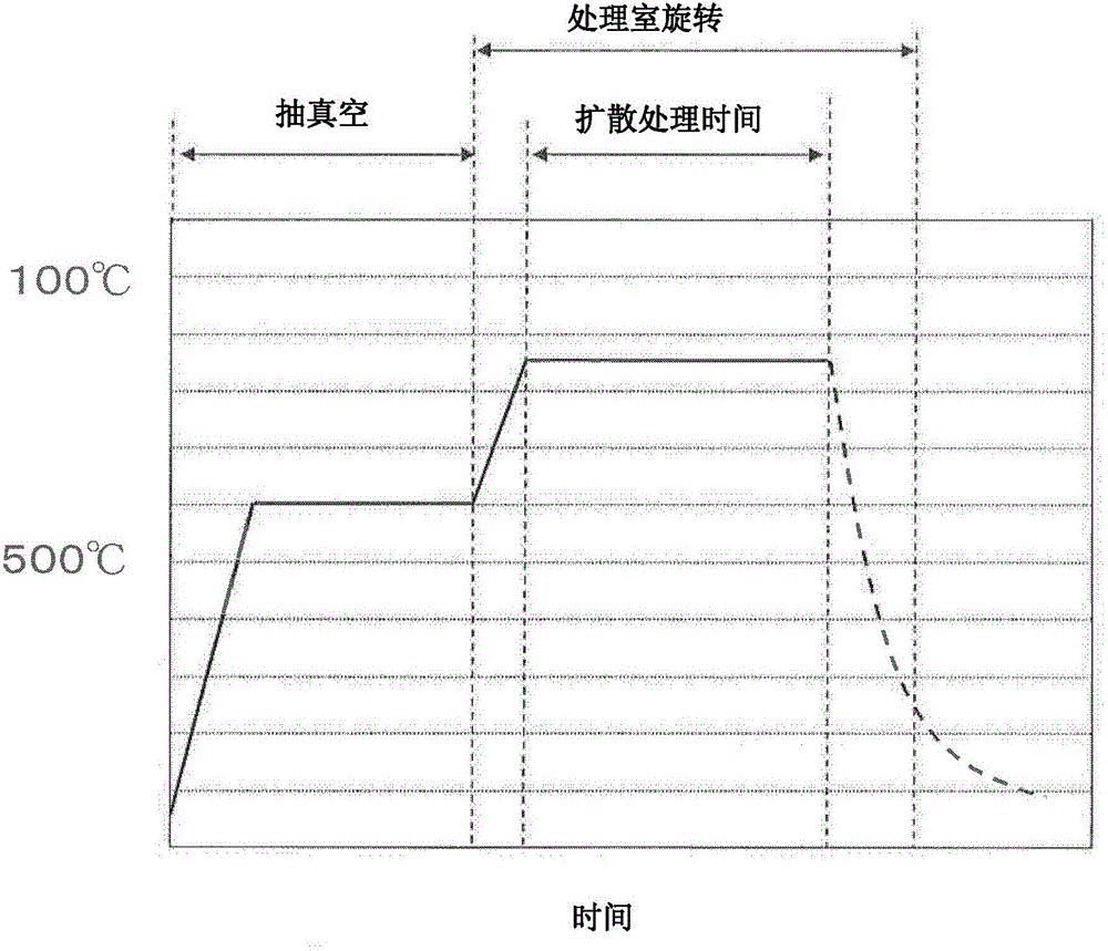
[0112] Next, use figure 2 The device is subjected to RH diffusion treatment. The inner diameter of the cylinder: about 300mm, the length of the cylinder: about 500mm, the input amount of the R-T-B type sintered magnet raw material: 5kg, the input weight of the RH diffusion source: 10kg, and the input...

experiment example 2

[0130]At first, make the R-T-B type sintered magnet raw material (in the table, magnet raw material Q ). By machining it, a cuboid R-T-B type sintered magnet raw material of 60 mm×4 mm×7 mm elongated in one direction was obtained. The magnetic properties of the prepared R-T-B type sintered magnet raw materials were measured by a B-H tracer. As a result, the coercivity H in the properties after heat treatment (500°C) cJ 1000kA / m, residual magnetic flux density B r It is 1.42T.

[0131] Next, diffusion treatment was performed using the same apparatus as in Experimental Example 1. Table 1 shows the conditions related to the type and input amount of the stirring auxiliary parts. The heat treatment conditions such as the heating mode, the atmosphere in the treatment chamber, the rotation speed of the treatment chamber, etc. are the same as those in Experimental Example 1.

[0132] The results of the experiments, the calculated chipping occurrence rates, and the measured magnet...

experiment example 3

[0139] Next, use TbFe as the RH diffusion source 3 (RH diffusion source β in the table) instead of DyFe 2 conduct experiment. The conditions of this example except using TbFe as RH diffusion source 3 instead of DyFe 2 Except for this point, the conditions were the same as those of Experimental Example 1. The detailed conditions are shown in Table 4.

[0140] H after diffusing the RH at 37 from the sample with only φ5 cJ The coercive force H within ±1% of the value of 1966kA / m cJ In the case of "○", the coercive force H will exceed -1% cJ The case of "×". The method of defect determination is the same as that of Experimental Example 1.

[0141] As shown in Table 4 below, the same effects as Experimental Example 1 were obtained in this Experimental Example. Therefore, it can be seen that according to the embodiment of the present invention, the effect is exerted regardless of the composition of the RH diffusion source.

[0142] In addition, it can be seen that the inc...


PUM

PropertyMeasurementUnit
diameteraaaaaaaaaa
diameteraaaaaaaaaa
diameteraaaaaaaaaa

Abstract

The invention provides a manufacturing method of an R-T-B sintered magnet. By adopting the method, a heavy rare earth element RH diffuses inwards from the surface of R-T-B sintered magnet raw materials without lowering the residula magnetic flux density, and the fracturing and damages of the R-T-B sintered magnet are inhibited. The manufacturing method comprises an R-T-B sintered magnet raw material preparing step, an RH diffusion source preparing step, a step for loading the R-T-B sintered magnet raw materials, RH diffusion sources and stirring auxiliary parts in a processing chamber; and an RH diffusion step for moving the R-T-B sintered magnet raw materials, the RH diffusion sources and stirring auxiliary parts and simultaneously heating the R-T-B sintered magnet raw materials and the RH diffusion sources. The size of each R-T-B sintered magnet raw material is larger than 1000mm3, and the maximum size is two times of the minimum size among the sizes in three orthotropic directions. Each RH diffusion source is smaller than 3 mm. The stirring auxiliary parts include a plurality of first ball bodies and a plurality of second ball bodies.

Description

technical field [0001] The present invention relates to having R 2 T 14 A method for manufacturing an R-T-B type sintered magnet (R is a rare earth element, and T is a transition metal element mainly composed of Fe) with a B-type compound as the main phase. Background technique [0002] with R 2 T 14 R-T-B type sintered magnets with a B-type compound as the main phase are known as the highest performance magnets among permanent magnets, and are used in various motors such as voice coil motors (VCM) for hard disk drives, motors for hybrid vehicles, and home appliances, etc. . [0003] The coercive force of R-T-B sintered magnets decreases at high temperature, so irreversible thermal demagnetization occurs. In order to avoid irreversible thermal demagnetization, it is required to maintain a high coercive force even at high temperature when used in a motor or the like. [0004] It is known that in R-T-B type sintered magnets, if the R 2 T 14 When a part of R in the B-ty...

Claims


Application Information

Patent Timeline
Patent Type & Authority Applications(China)
IPC IPC(8): H01F41/02
CPCH01F41/0293
Inventor 山方亮一小林浩也国吉太
Owner HITACHI METALS LTD
Why Eureka
Try Eureka