
Metal-based composite material shearing strength testing method and sample preparation method

A composite material and test method technology, which is applied in the preparation of test samples and the use of applied stable shear force to test the strength of materials, etc. Matrix composite material shear strength and other issues, to achieve accurate measurement and avoid hardening effect

Inactive Publication Date: 2016-10-19
江苏省(丹阳)高性能合金材料研究院
View PDF1 Cites 18 Cited by
  • Summary
  • Abstract
  • Description
  • Claims
  • Application Information

AI Technical Summary

Problems solved by technology

[0003] Although many works have been carried out to study the structure and bonding strength of metal matrix composites, especially the composite interface of discontinuously reinforced metal matrix composites, the main research work is limited to inferring the interface bonding from the observation of the microstructure of the interface. , and rely on specific assumptions or simplified models, under certain model assumptions, the interface bonding strength matching the specific experimental data can be obtained through data fitting and numerical calculation, but there is no one that can accurately measure the interface bonding of metal matrix composites. Effective methods and techniques for strength, and the preparation of test specimens is the key to restricting the testing of shear strength of metal matrix composites. How to prepare suitable test specimens and establish an effective quantitative test and evaluation method for interfacial bonding strength To provide accurate and direct quantitative data support for theoretical modeling and calculation to explain the "interface-performance" coupling relationship has become a technical problem to be solved by those skilled in the art

Method used


Image

  • Metal-based composite material shearing strength testing method and sample preparation method
  • Metal-based composite material shearing strength testing method and sample preparation method
  • Metal-based composite material shearing strength testing method and sample preparation method

Examples


Embodiment 1

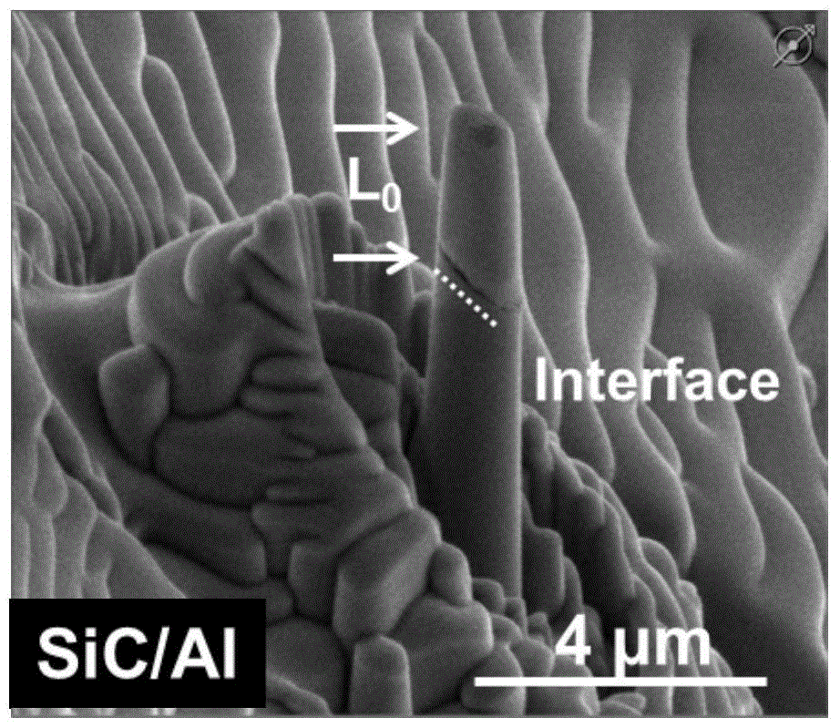
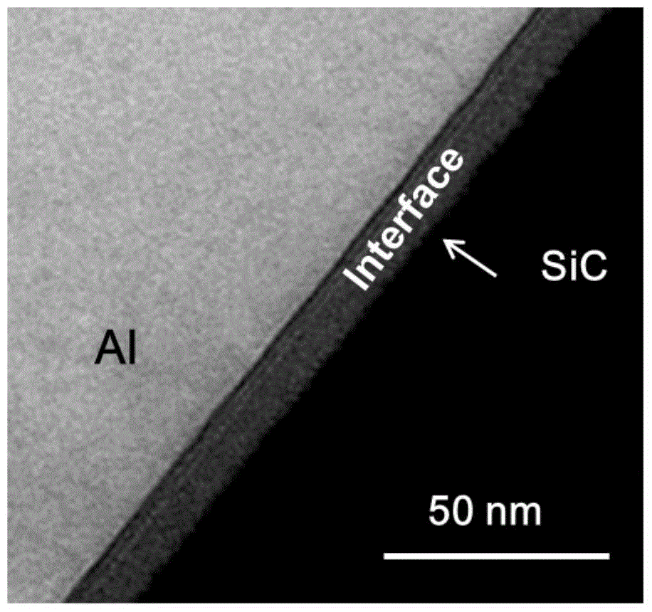
[0033] Aluminum-based silicon carbide particle-reinforced composite materials fully combine the different advantages of silicon carbide ceramics and metal aluminum. They have high thermal conductivity, a thermal expansion coefficient that matches the chip, low density, light weight, high hardness and high flexural strength. The leader in the new generation of electronic packaging materials meets the requirements of lightweight and high-density packaging, and is suitable for applications in aviation, aerospace, high-speed rail and microwave fields. In this embodiment, aluminum-based silicon carbide (SiC / Al) is used for specific description.

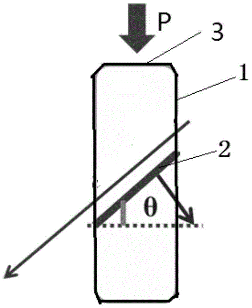
[0034] Such as figure 1 As shown, a micronano-sized pillar 1 containing a single reinforcement-matrix interface 2 is etched using FIB. The included angle is θ, the pressure applied on the top surface 3 of the cylinder along the axial direction of the cylinder is P, the pressure of the cylinder along its axial direction is P / A, and the cro...


PUM

PropertyMeasurementUnit
Diameteraaaaaaaaaa

Abstract

The invention relates to a metal-based composite material shearing strength testing method and a preparation method of a sample applied in the testing method. According to the principle, a micro-nano size cylinder containing a separate reinforcement-substrate interface is etched by means of focused ion beams, the reinforcement-substrate interface of the micro-nano size cylinder and the axial direction of the cylinder form a 45-degree angle, pressure is exerted on the top surface of the micro-nano size cylinder in the axial direction by using a nanoindentor, and the micro-nano size cylinder is compacted and deformed; in the process, the direction, forming 45 degrees with the compaction direction, of the reinforcement-substrate interface will bear the maximum shearing strength till the shear behavior occurs on the reinforcement-substrate interface, and the shearing strength of the reinforcement-substrate interface is calculated according to a stress-strain curve, recorded through the nanoindentor, of the micro-nano size cylinder.

Description

technical field [0001] The invention relates to a method for effectively testing the shear strength of a reinforcing body and a matrix interface in a metal matrix composite material, and a method for preparing a sample used in the test method, belonging to the field of metal matrix composite materials. Background technique [0002] The interface between the reinforcement and the matrix in metal matrix composites is the "link" connecting the two, and the "bridge" for the transfer of mechanical and other functions, such as thermal conductivity, electrical conductivity, and damping, between the two. Therefore, the interface structure, interface bonding strength and the properties of interface micro-domains are the key factors affecting the performance of metal matrix composites. However, the structure and bonding mode of the reinforcement-matrix interface are quite complex and highly dependent on the type, original state and preparation process of the reinforcement phase; Due ...

Claims


Application Information

Patent Timeline
IPC IPC(8): G01N3/24G01N1/28
CPCG01N3/24G01N1/28
Inventor 郭强魏剑辉郭晓雷
Owner 江苏省(丹阳)高性能合金材料研究院
Learn More