In-boiler desulfurization and denitration system and method for chain grate boiler

A technology for desulfurization and denitrification, and furnace desulfurization, which is applied in separation methods, chemical instruments and methods, and separation of dispersed particles. It can solve problems such as scaling and corrosion of heat exchange equipment, lack of reaction space, and large temperature ranges, and achieve nitrogen reduction. The formation of oxides, the improvement of denitrification efficiency, and the effect of preventing moisture absorption and agglomeration

Active Publication Date: 2016-10-26
SHANDONG SHENHUA SHANDA ENERGY ENVIRONMENTAL +1
View PDF10 Cites 13 Cited by
  • Summary
  • Abstract
  • Description
  • Claims
  • Application Information

AI Technical Summary

Problems solved by technology

This method can improve desulfurization efficiency, but it only involves injection desulfurization in the furnace, and cannot realize injection denitrification in the furnace
In addition, due to the small capacity and unstable combustion of the chain furnace, the lack of reaction space and the unstable combustion lead to a wide range of temperature changes in the furnace, the selective non-catalytic reduction technology (SNCR ) The efficiency is relatively low and unstable, and in severe cases, the scale and corrosion of heat exchange equipment will be caused by the large amount of ammonia escape

Method used


Image

  • In-boiler desulfurization and denitration system and method for chain grate boiler
  • In-boiler desulfurization and denitration system and method for chain grate boiler

Examples


Embodiment 1

[0043] The concentration of sulfur dioxide pollutants in the chain furnace is 1000mg / Nm 3 , 9% oxygen content, the concentration of nitrogen oxides is 200mg / Nm 3 .

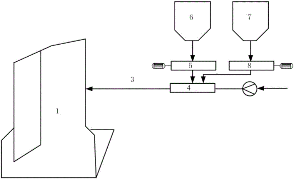
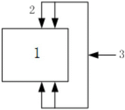
[0044] The required desulfurizer and denitrification agent are added to the smoke powder mixer 4 through the first frequency conversion screw feeder 5 and the second frequency conversion screw feeder 8, and the mass ratio of the desulfurizer and denitrification agent in the mixing bin is 2 : 1; the variable frequency fan 9 leads the flue gas at the boiler tail (the temperature is about 150°C) to the smoke powder mixer 4 to realize the mixing of flue gas, calcium-based desulfurizer and urea powder, and then the calcium-based desulfurizer and urea powder are transported to The injection main pipe 3 divides the desulfurization agent and urea powder through four injection branch pipes 2, and transports them to the hearth of the chain furnace 1 for desulfurization and denitrification. The temperature of the hearth at ...

Embodiment 2

[0051] The furnace temperature at the input point is 1000° C., and the others are the same as in Example 1. The desulfurization efficiency of the final flue gas reaches 80%, and the denitrification efficiency reaches 55%.


PUM


Abstract

The invention discloses an in-boiler desulfurization and denitration system and method for a chain grate boiler. The system comprises the chain grate boiler, a feed bin and a smoke and powder mixer, wherein the feed bin is used for providing a space for containing a desulfurization agent and/or a denitration agent; the smoke and powder mixer is connected with the feed bin, a flue gas pipeline and the chain grate boiler respectively; flue gas is mixed with the desulfurization agent and the denitration agent in the smoke and powder mixer to provide power to deliver the desulfurization agent and the denitration agent to an injection pipeline component mounted in the chain grate boiler for injection; the desulfurization agent and the denitration agent are a calcium-based desulfurization agent and urea powder respectively. The desulfurization agent and the denitration agent are delivered into the chain grate boiler through the tail flue gas of the boiler, so that the urea powder can be effectively prevented from absorbing moisture for agglomeration; in addition, compared with that of hearth flue gas, the temperature and oxygen content of the tail flue gas are lower, so that an area of which the temperature is relatively proper and the oxygen concentration is relatively lower can be provided for denitration reaction in a higher-temperature area of a hearth, and the problems of instable hearth temperature, small reaction space and the like of the chain grate boiler can be solved.

Description

technical field [0001] The invention relates to the technical field of flue gas pollutant control, in particular to a desulfurization and denitrification system and method in a chain furnace. Background technique [0002] At present, there are about 500,000 coal-fired industrial boilers in my country, and the annual coal consumption accounts for more than 20% of the total annual coal consumption in the country, of which more than 40% are chain grate boilers. The average operating efficiency of coal-fired industrial boilers is about 65%, which is far lower than that of coal-fired power plant boilers. Affected by problems such as low combustion efficiency and imperfect pollutant control systems, coal-fired industrial boilers emit relatively high pollutants, and their SO 2 and NOx emissions are second only to power plant boilers, and even the pollution caused by industrial boiler emissions in key cities across the country has surpassed power plant boilers. [0003] In-furnace ...

Claims


Application Information

Patent Timeline
Patent Type & Authority Applications(China)
IPC IPC(8): B01D53/83B01D53/56B01D53/50
CPCB01D53/508B01D53/565B01D2251/2067B01D2251/404
Inventor 吴华崔琳李敏张立强徐夕仁崔振林
Owner SHANDONG SHENHUA SHANDA ENERGY ENVIRONMENTAL
Why Eureka
Try Eureka