Powder material laser-sintering forming device

A technology of laser sintering and powder materials, which is applied in the direction of additive processing, additive manufacturing, and energy efficiency improvement. It can solve the problems of insufficient preheating temperature control accuracy, lower product quality, and low preheating temperature accuracy, so as to improve quality and Improve production efficiency, improve preheating efficiency, and have a wide range of applications

Active Publication Date: 2016-10-26
ZHONGBEI UNIV
View PDF7 Cites 44 Cited by
  • Summary
  • Abstract
  • Description
  • Claims
  • Application Information

AI Technical Summary

Problems solved by technology

[0004] At present, in the SLS forming process, there are still the following problems to be solved: ① It is difficult to monitor the powder quality
The quality of powder spreading has an important influence on the quality of formed parts. When powder spreading is uneven, it is easy to cause internal defects of formed parts, thereby reducing product quality and even waste products
[0005] ② It is difficult to monitor whether the warping deformation of the formed part occurs during the forming process. During the forming process, when the part warps and deforms, if it cannot be found in time and the process parameters are adjusted in time, the degree of deformation will become more and more serious, resulting in forming failure
[0006] ③ The preheating of the formed powder is uneven and the accuracy of the preheating temperature is low. There are two main heat sources for the preheating of the powder during the powder spreading process. preheating
Due to the different sizes of the formed parts, the temperature distribution in dif...

Method used


Image

  • Powder material laser-sintering forming device
  • Powder material laser-sintering forming device
  • Powder material laser-sintering forming device

Examples


Embodiment Construction

[0028] In order to make the technical problems, technical solutions and beneficial effects to be solved by the present invention clearer, the present invention will be further described in detail below in conjunction with the accompanying drawings and embodiments. It should be understood that the specific embodiments described here are only used to explain the present invention, not to limit the present invention.

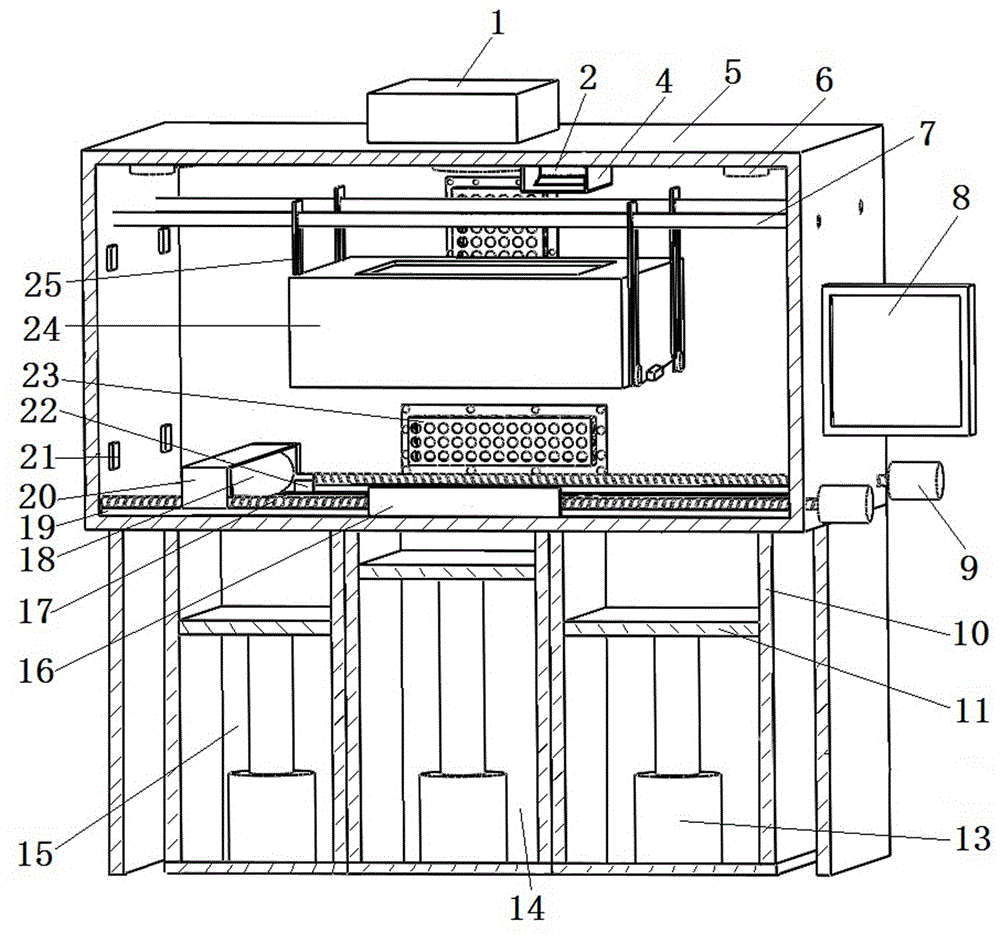
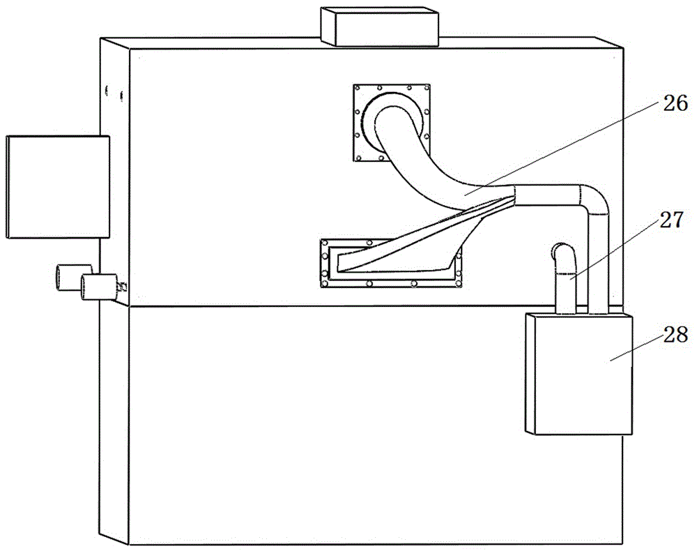
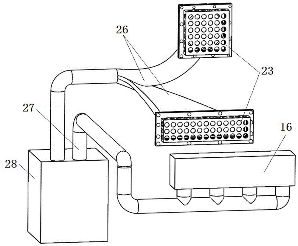
[0029] like figure 1 , Figure 7 to Figure 9 As shown, the powder material laser sintering forming device includes a molding cavity 5, and the bottom of the molding cavity 5 is provided with a collection cylinder 15, a molding cylinder 14 and a powder supply cylinder 10, and the molding cylinder 14 is located at the collection cylinder 15 and the powder supply cylinder 10. Between, the collecting cylinder 15, the forming cylinder 14 and the powder supply cylinder 10 are all provided with a hydraulic cylinder 13, the piston rod of the hydraulic cylinder 13 is provi...


PUM


Abstract

The invention relates to a powder material laser-sintering forming device, belongs to the technical field of 3D printing additive manufacturing technologies and provides a powder material laser-sintering forming device which is simple to operate, high in powder spreading efficiency, good in powder spreading effect and wide in application range. The powder material laser-sintering forming device adopts the technical scheme that hydraulic oil cylinders are arranged in a material collecting cylinder, a forming cylinder and a powder supply cylinder; material pushing baffles are arranged on the hydraulic oil cylinders; powder spreading sliding rails are arranged in the middle of a forming cavity; a roller rack is mounted on the powder spreading sliding rails in a sliding way; a powder spreading roller is mounted on the roller rack; roller rack lead screws are arranged on the roller rack; preheating guide rails are arranged at the upper part of the forming cavity; a preheating housing is mounted on the preheating guide rails in a sliding way; preheating rods are arranged in the preheating housing; an infrared thermometer is arranged outside the preheating housing; a laser scanning system is arranged at the top of the forming cavity; and a gas intake and exhaust device is arranged on the side wall of the forming cavity. The powder material laser-sintering forming device is widely used for laser-sintering forming of powder material.

Description

technical field [0001] The invention relates to a powder material laser sintering forming device, which belongs to the technical field of 3D printing additive manufacturing. Background technique [0002] In recent years, 3D printing technology has set off a 3D printing boom in academia and industry with its unique advantages. 3D printing is based on the three-dimensional model, using polymer plastics, photosensitive resin, metal powder, film-coated powder and other materials as raw materials, and realizes the manufacture of three-dimensional models through the principle of layer-by-layer superposition of materials, integrating CAD, mechanical automation and other technologies , has the characteristics of rapidity, high flexibility, and high efficiency, and is especially suitable for manufacturing complex structural models in small batches. Its products have been used in automobile manufacturing, aerospace and other fields. [0003] Selective laser sintering (SLS) technology...

Claims


Application Information

Patent Timeline
IPC IPC(8): B22F3/105B29C67/00C04B35/64B33Y30/00B33Y50/02
CPCC04B35/64B33Y30/00B33Y50/02B22F10/00B22F12/63B22F10/28B22F12/49B22F10/362B22F12/224B22F12/90B22F12/70B22F12/13B22F10/77Y02P10/25
Inventor 白培康赵占勇李玉新刘斌王建宏刘增禄
Owner ZHONGBEI UNIV
Why Eureka
Try Eureka