Gradual type laser shock continuous riveting method and device

A laser shock and progressive technology, applied in the direction of laser welding equipment, welding equipment, metal processing equipment, etc., can solve the problem of damage to material integrity and sealing, small size of mechanical interlocking structure parts, difficulty in controlling the direction of lateral force, etc. Problems, avoid electrochemical corrosion, improve surface quality, and have a large degree of deformation

Active Publication Date: 2016-10-26
SHANDONG UNIV
View PDF8 Cites 8 Cited by
  • Summary
  • Abstract
  • Description
  • Claims
  • Application Information

AI Technical Summary

Problems solved by technology

[0006] (2) Destroying the integrity and sealing of the material, it is easy to cause uneven force on the connection part, thus causing damage at the connection position
[0007] (3) Not resistant to high temperature, low connection strength
[0008] (4) easy to corrode
[0013] (3) There is still a certain thermal effect;
[0014] (4) The forming device is relatively simple, and the formation of the mechanical interlocking structure between the two layers is completely dependent on the lateral force generated during the plasma explosion, and the direction of the lateral force is difficult to control, so the size of the formed mechanical interlocking structure is often Relatively small, so it is not easy to achieve high connection strength

Method used


Image

  • Gradual type laser shock continuous riveting method and device
  • Gradual type laser shock continuous riveting method and device
  • Gradual type laser shock continuous riveting method and device

Examples


Embodiment

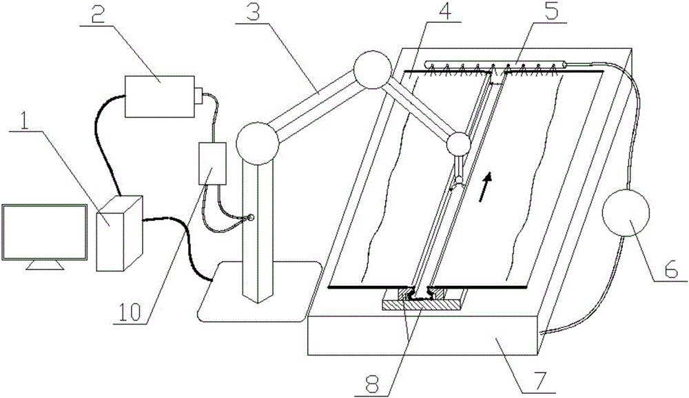
[0053]Embodiment: a kind of progressive laser shock continuous riveting device, its structure is as follows figure 1 As shown, it includes a control module 1, a pulse laser 2 connected to the control module and an articulated robot 3, a water storage tank 7 on one side of the joint robot 3, a water curtain generator 5 installed on the water storage tank 7, and The water pump 6 used to pump the water in the water storage tank 7 to the water curtain generator 5.

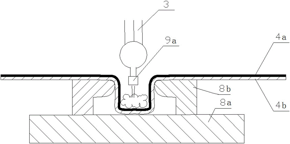
[0054] A forming mold 8 is installed on the water storage tank 7, and the forming mold includes a base 8a; two L-shaped support frames 8b inverted on the base, and the non-closed space formed by the two L-shaped support frames and the base is formed by plates. The forming cavity of the lock structure.

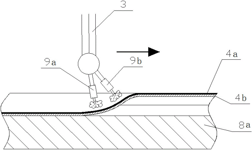
[0055] The pulsed laser 2 can output pulsed lasers with adjustable parameters, which are divided into at least two beams by the optical splitting system 10, and transmitted to the first laser focusing lens 9a and the s...


PUM


Abstract

The invention relates to a gradual type laser shock continuous riveting method and device and belongs to the technical field of material connection. The method and device are used for linear riveting between boards. The method includes the steps that A, a laser device is used for directly generating multiple beams of lasers or a beam splitting system is used for generating the multiple beams of lasers; B, a V-shaped included angle is formed between the extending lines of every two laser beams, and the boards are swept through the multiple beams of lasers at the same time; C, when the pulse lasers act on the surfaces of the boards, exploding plasma is generated, and each board gradually deforms to be of a groove structure under the shock effect of the exploding plasma and with the cooperation of the restraint of a forming die; D, the arranging manner of the multiple beams of lasers is adjusted, so that the laser beams are aligned with the two sides of the bottom of each groove structure; and E, the multiple beams of lasers move; under the continuous shock effect of the exploding plasma, the laser beams are matched with the restraint of the forming die, so that the groove structures are gradually shocked into interlocking structures; and the step B to the step E are repeated, the boards are gradually shocked, and therefore the boards are riveted together.

Description

technical field [0001] The invention relates to the technical field of material connection, in particular to a progressive laser shock continuous riveting method and device. Background technique [0002] Material connection technology is one of the widely used technologies in the field of mechanical manufacturing. Up to now, material connection technology has a considerable number of specific application methods, and the classification standards are also varied. According to the basic principle of connection realization, it can be divided into mechanical connection and physical and chemical connection. [0003] Common mechanical connection methods include: bolt connection, screw connection, rivet connection, key connection, pin connection, etc. Common physical and chemical connection methods include: glue bonding, welding, sealing, etc. The difference lies in the main process of realizing the connection Whether there is a change in physical state (such as solid-liquid phase ...

Claims


Application Information

Patent Timeline
IPC IPC(8): B23K26/0622B23K26/70B21D39/03
CPCB21D39/031B23K26/0622B23K26/702
Inventor 季忠王建峰梁萌刘韧郑超
Owner SHANDONG UNIV
Why Eureka
Try Eureka