Electromagnetic valve sinking oil sprayer

A fuel injector and solenoid valve technology, which is applied in the directions of machines/engines, fuel injection devices, and engine components, can solve the problems of small installation space for solenoid valves, high processing costs, and difficulty in ensuring processing accuracy, so as to ensure processing quality. , The effect of low processing cost

Active Publication Date: 2016-10-26
CHINA FAW LIMITED WUXI FUEL INJECTIONEQUIP RES INST +1
View PDF4 Cites 7 Cited by
  • Summary
  • Abstract
  • Description
  • Claims
  • Application Information

AI Technical Summary

Problems solved by technology

However, the closer to the fuel injector, the smaller the structural size, and the high-pressure oil passage must be arranged at the same time, resulting in a smaller installation space for the solenoid valve. At the same time, the injection pressure of the existing fuel injector continues to increase, and the requirements for electromagnetic force are also getting higher and higher.
Therefore, for the solenoid valve sinking injector, the installation and arrangement of the solenoid valve become more and more difficult
[0004] The invention application with the application number CN201510167428 discloses a fuel injector that improves the efficiency of the electromagnetic actuator. The disadvantage of this structure is that the armature and the armature rod are eccentric structures relative to the injector body
The axis of the inclined oil passage is not vertical to the end face of the orifice plate, which is difficult to process, and the flow stability of the oil outlet hole is not as good as that of the straight hole structure, which will affect the performance of the injector
[0005] And the inclined oil path will make the ball valve be affected by the impact force of asymmetric liquid, which will make the stability of the ball valve worse
[0006] The sealing cone is an important structure for the ball valve to switch. The sealing surface is eccentric relative to the orifice plate, which makes it difficult to guarantee the machining accuracy due to the need for counterweight due to the rotation during the machining process. The machining cost is higher and the difficulty is greater.

Method used


Image

  • Electromagnetic valve sinking oil sprayer
  • Electromagnetic valve sinking oil sprayer
  • Electromagnetic valve sinking oil sprayer

Examples


Embodiment Construction

[0028] The present invention is described in further detail now in conjunction with accompanying drawing. These drawings are all simplified schematic diagrams, which only illustrate the basic structure of the present invention in a schematic manner, so they only show the configurations related to the present invention.

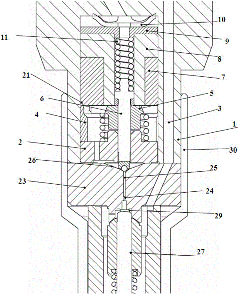
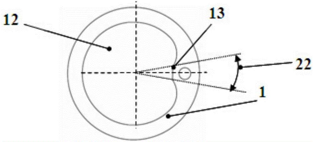
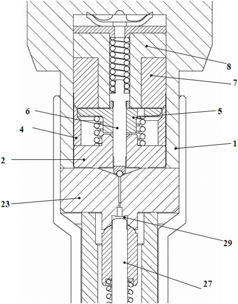
[0029] like Figure 1~Figure 3 As shown, a solenoid valve sinking fuel injector includes a fuel injector body 1, a control valve seat 2, an adjustment ring 4, an armature 5, and an electromagnet assembly. The interior of the fuel injector body 1 is a cylindrical cavity structure, The control valve seat 2, the adjustment ring 4, the armature 5, and the electromagnet assembly are all installed in the cylindrical cavity of the fuel injector; the leaf spring 10, the electromagnet assembly, the armature 5, and the control valve seat are installed from top to bottom in the cylindrical cavity 2. The T-shaped spring seat is located between the leaf spring 10 and the ...


PUM


Abstract

The invention discloses an electromagnetic valve sinking oil sprayer. The electromagnetic valve sinking oil sprayer comprises an oil sprayer body, a control valve seat, an adjusting ring, an armature and an electromagnet assembly. The inside of the oil sprayer body is of a structure of a cylindrical cavity. The control valve seat, the adjusting ring, the armature and the electromagnet assembly are all installed in the cylindrical cavity of the oil sprayer. A radial protruding structure is arranged in the position, adjacent to a high-pressure oil inlet channel, on the inner wall face of the cavity of the oil sprayer body and directly extends from the bottom of the cavity to the top in the axial direction of the oil sprayer body. The control valve seat, the adjusting ring, the armature and the electromagnet assembly are al provided with grooves corresponding to the protruding structure. The armature, an armature rod, a ball valve, a sealing cone face, an oil pump capacity hole and a high-pressure oil channel can be arranged on the same axis, and the axis coincide to the axis of the oil sprayer body. The installation space of an electromagnet is further enlarged in a limited space while the installation requirement of the sinking oil sprayer is met.

Description

technical field [0001] The invention belongs to the field of fuel injection systems of internal combustion engines, and in particular relates to a solenoid valve sinking type fuel injector. Background technique [0002] As emission regulations become more and more stringent, higher requirements are put forward for diesel engines. The spray combustion process needs to be controlled more precisely and flexibly. The common rail fuel system is required to have multiple injection capabilities, that is, to improve the response speed of fuel injection. and precision. [0003] Solenoid valve sunken fuel injector is adopted, and the electromagnet is installed as close as possible to the fuel injection nozzle, the length of the control piston and needle valve is shortened, and the mechanical hydraulic delay from the solenoid to the fuel injection nozzle is reduced, which can greatly improve the fuel injection. The response speed of the oiler. However, the closer to the fuel injector...

Claims


Application Information

Patent Timeline
Patent Type & Authority Applications(China)
IPC IPC(8): F02M51/06F02M61/10
CPCF02M51/0614F02M61/10
Inventor 郭立新宋永平缪雪龙
Owner CHINA FAW LIMITED WUXI FUEL INJECTIONEQUIP RES INST
Why Eureka
Try Eureka