
Phosphor, light emitting element, and light emitting device

A technology for light-emitting elements and phosphors, applied in the field of phosphors, can solve problems such as difficulty in achieving high brightness, and achieve the effects of high color rendering and color reproducibility, excellent moisture resistance, and long life.

Inactive Publication Date: 2016-10-26
DENKA CO LTD
View PDF8 Cites 2 Cited by
  • Summary
  • Abstract
  • Description
  • Claims
  • Application Information

AI Technical Summary

Problems solved by technology

[0005] However, for activated Eu 2+ Phosphors, which are luminescent central ions, have a wide half-value width of the luminescence spectrum, so there is a tendency to contain many spectral components in the wavelength band beyond the visible range of humans, making it difficult to achieve high luminance

Method used


Image

  • Phosphor, light emitting element, and light emitting device
  • Phosphor, light emitting element, and light emitting device
  • Phosphor, light emitting element, and light emitting device

Examples


Embodiment 1~3 and comparative example 1

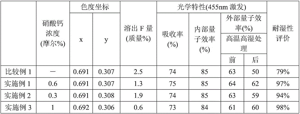
[0059] Examples 1 to 3 and Comparative Example 1 all involve the general formula: A 2 MF 6 : Mn 4+ Indicates the phosphor whose element A is K, element M is Si, F is fluorine, and Mn is manganese. 2 SiF 6 : Mn 4+ Represents the phosphor. Comparative Example 1 is a conventional phosphor that does not contain a Ca-containing compound on the surface of the particles, and Examples 1 to 3 are phosphors that contain a Ca-containing compound on the surface of the particles and are surface-modified.

[0060]

[0061] At room temperature, 500 ml of hydrofluoric acid with a concentration of 48% by mass was put into a beaker made of Teflon (registered trademark) with a capacity of 1 liter, and K 2 SiF 6 Powder (manufactured by Wako Pure Chemical Industries, Ltd., grade: for chemical use) 50g and K synthesized by the aforementioned method 2 MnF 6 Powder 5g, prepare suspension.

[0062] A beaker made of Teflon (registered trademark) containing the suspension was placed on a hot plate and heated ...

Embodiment 2 and 3

[0068] In Examples 2 and 3, the method and conditions were exactly the same as in Example 1, except that the concentration of the calcium nitrate aqueous solution added to the phosphor suspension was changed to 0.3 mol% and 1 mol%, respectively.

[0069]

[0070] Next, the obtained phosphor was evaluated by the following method.

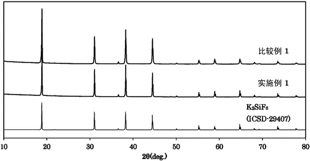
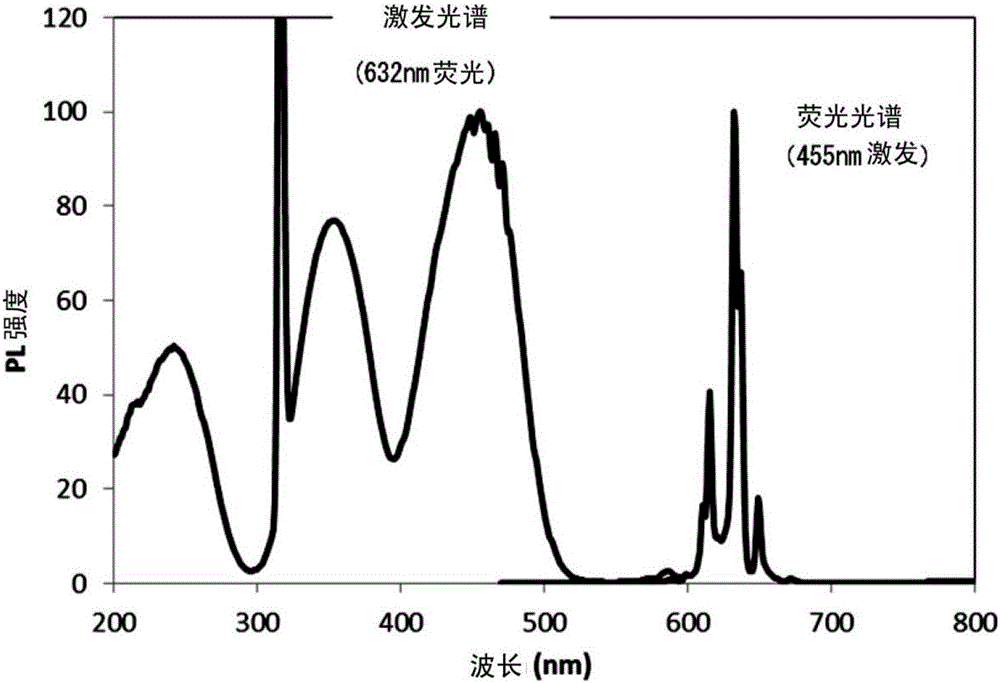
[0071] First, for the phosphors of Comparative Example 1 and Examples 1 to 3, the crystal phase, excitation spectrum / fluorescence spectrum, quantum efficiency, chromaticity coordinates, eluted F amount, and moisture resistance were evaluated. The evaluation results are shown in Table 1 and Figure 1~2 .

[0072] [Table 1]

[0073]

[0074]

[0075] The X-ray diffraction pattern of the phosphor was measured using an X-ray diffraction apparatus (Ultima IV manufactured by Rigaku Corporation). CuKα tube was used for the measurement.

Embodiment 4

[0098] A light-emitting element having the phosphor of Example 1 and a cyan light-emitting LED as a light-emitting source was produced. Since this light-emitting element uses the phosphor of Example 1 which is excellent in moisture resistance, it is excellent in color rendering and color reproducibility. In addition, compared with the light-emitting element using the phosphor of Comparative Example 1, the brightness reduction caused by the passage of time is less.


PUM


Abstract

The present invention pertains to the following: a phosphor in which humidity resistance is improved by modifying the particle surface of an Mn4+ activated complex fluoride phosphor which can achieve high luminance red-color light emission; and a light emitting element and a light emitting device which excel in color rendering properties and in stability as a result of using such phosphor. This phosphor is represented by general formula A2MF6:Mn4+. Element A is an alkali metal element containing at least K. Element M is at least one type of metal element selected from among Si, Ge, Sn, Ti, Zr, and Hf. F is fluorine and Mn is manganese. The phosphor is characterized in that the particle surface thereof is modified so that the content of fluorine in a supernatant liquid is no more than 2 wt%, the supernatant liquid being obtained after dispersing fluorine in a methanol water mixture (with a water content of 10 mass%) of 100 parts by mass ratio and leaving the same to stand for 10 minutes.

Description

Technical field [0001] The present invention relates to a phosphor that is excited by ultraviolet or blue light to emit red light, a light-emitting element using the phosphor, and a light-emitting device using the light-emitting element. In more detail, it relates to Mn whose moisture resistance is improved by modifying the particle surface 4+ An activated composite fluoride phosphor, and a light-emitting element and a light-emitting device having excellent color rendering properties and stability by using the phosphor. Furthermore, the present invention also relates to the evaluation of Mn 4+ A method to activate the moisture resistance of the composite fluoride phosphor. Background technique [0002] As white LEDs, white LEDs that combine blue LED chips and yellow phosphors to obtain pseudo-white light are widely used. However, although the white LED of this method falls into the white area as its chromaticity coordinate value, the luminous components such as the red area are ...

Claims


Application Information

Patent Timeline
Patent Type & Authority Applications(China)
IPC IPC(8): C09K11/61C09K11/08H01L33/50
CPCC09K11/617H01L33/502C09K11/57
Inventor 市川真義江本秀幸柳慎一伊藤和弘
Owner DENKA CO LTD
Learn More