Sawtooth jet type evacuator

A sawtooth and nozzle technology, applied in the direction of jet pumps, jet devices, jet devices, etc., can solve the problems of large steam consumption, small steam consumption, no research on improving the injection coefficient and evacuation efficiency of steam ejectors, etc. Improvement of injection coefficient and work efficiency, effect of improved flow form, high injection coefficient and work efficiency

Inactive Publication Date: 2016-11-02
苏州中尧节能环保设备有限公司
View PDF7 Cites 11 Cited by
  • Summary
  • Abstract
  • Description
  • Claims
  • Application Information

AI Technical Summary

Problems solved by technology

The larger the diameter of the nozzle throat, the larger the steam consumption, and the smaller the diameter of the nozzle throat, the smaller the steam consumption. Howeve

Method used


Image

  • Sawtooth jet type evacuator
  • Sawtooth jet type evacuator
  • Sawtooth jet type evacuator

Examples


Embodiment Construction

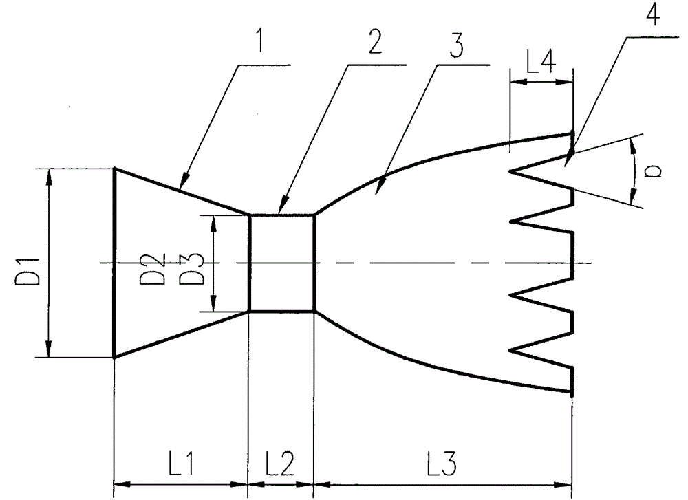
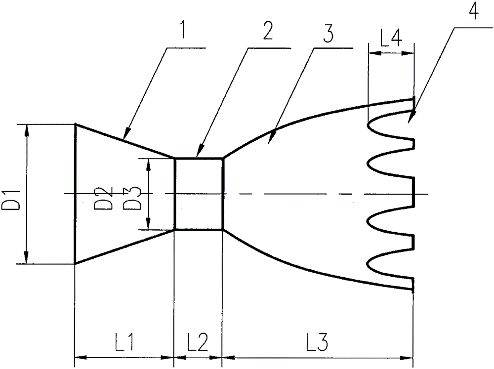
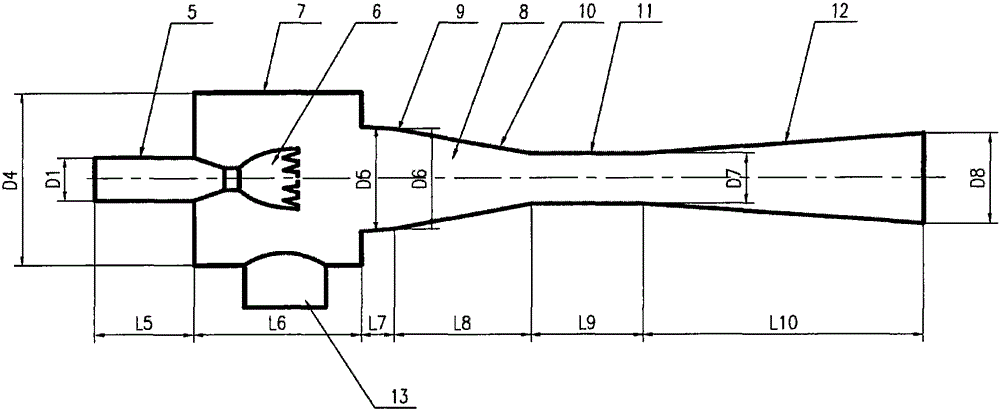
[0022] Will figure 1 or figure 2 The 3 parts of the serrated nozzle: the nozzle inlet section ( figure 1 , 2 Symbol 1), nozzle throat ( figure 1 , 2 Symbol 2), nozzle outlet section ( figure 1 , 2 Symbol 3) are connected in sequence to form a complete supersonic sawtooth nozzle structure. Then, the complete supersonic sawtooth nozzle ( image 3 Symbol 6) is installed in the suction chamber ( image 3 In the symbol 7), the inlet section of the sawtooth nozzle ( figure 1 , 2 Symbol 1) and the inlet section of the mainstream fluid (such as water vapor, air, process fluid) pipeline ( image 3 The joints in symbol 5) are welded, or gasketed and threaded, or gasketed and flanged; the process piping that needs to be sucked in the process device is welded, or gasketed and threaded, or gasketed Plate seal and flanged to the secondary inlet ( image 3 Middle symbol 13); the outlet of the diffuser section of the mixing diffuser chamber ( image 3 The middle symbol 12) is we...


PUM


Abstract

The invention discloses a supersonic sawtooth nozzle and a sawtooth jet type evacuator installing the same. The supersonic sawtooth nozzle comprises an inlet section, a nozzle throat, a nozzle outlet section and a triangular or concave fan-shaped modified profile at the tail edge of a nozzle outlet. The sawtooth jet type evacuator installing the supersonic sawtooth nozzle comprises: 1) a main fluid pipeline inlet section; 2) the supersonic sawtooth nozzle; 3) a suction chamber and a secondary fluid inlet which is connected with the suction chamber; and 4) a mixed diffusion chamber, wherein the mixed diffusion chamber is composed of: 1) a mixed section which is composed of two parts which are an inlet part and a contraction part; 2) a throat; and 3) a diffusion section. According to the supersonic sawtooth nozzle and the sawtooth jet type evacuator installing the same, the ejection coefficient and the working efficiency are high in mechanism and effect, and energy conservation and consumption reduction can be dramatically carried out.

Description

technical field [0001] The invention belongs to the technical fields of petroleum, petrochemical, chemical, metallurgy, electric power, refrigeration, pharmaceutical, seawater desalination and other industry equipment, and in particular relates to a supersonic sawtooth nozzle and a sawtooth jet evacuator for generating vacuum. [0002] Furthermore, the invention relates to an ejector vacuum pump for generating a vacuum. [0003] Furthermore, the invention relates to an injector or an injector pump for conveying fluids. Background technique [0004] The evacuator is composed of a fluid medium (called the main flow) at a certain pressure and temperature. After being decompressed and accelerated by the Laval (Laval) nozzle, it enters the mixing and diffusing chamber. flow) for energy exchange and mixing, and carry the pumped fluid in the mixing diffuser chamber to decelerate, mix, pressurize, and finally overcome the outlet back pressure to discharge, so as to achieve the purp...

Claims


Application Information

Patent Timeline
IPC IPC(8): B05B1/34F04F5/46F04F5/20
Inventor 刘友宏
Owner 苏州中尧节能环保设备有限公司
Why Eureka
Try Eureka