Eureka AIR delivers breakthrough ideas for toughest innovation challenges, trusted by R&D personnel around the world.

Friction stir welding tool with press-in depth and vibration feedback function

A technology of friction stir welding and vibration feedback, applied in welding equipment, manufacturing tools, non-electric welding equipment, etc., can solve the problems of welding seam defects, welding seam tail, high pressure, uncontrollable and detection, etc., to achieve reliable data and ensure stability Effects on sex and safety

Active Publication Date: 2016-11-09
JIANGSU UNIV OF SCI & TECH
View PDF6 Cites 5 Cited by
  • Summary
  • Abstract
  • Description
  • Claims
  • Application Information

AI Technical Summary

Problems solved by technology

Although the friction stir welding method can be used to obtain high-quality welded joints, in actual engineering operations, there are often weld defects and "keyholes" at the tail of the weld
[0003] With the rapid development of auxiliary means of welding technology, the development of robot technology is becoming more and more mature, but the existing friction stir welding equipment does not have a measurement and control system, which cannot properly measure the displacement, pressure, torque of the stirring needle and vibration of the friction stir welding machine during the welding process. Control and detection, for example, the existing PID pressure control scheme will cause excessive pressure, cause excessive flash, and there will be a large time lag at the same time, and the effect is not good; at the same time, the existing friction stir welding equipment is generally large in size and weight , it is difficult to install directly on the end of the robot arm

Method used


Image

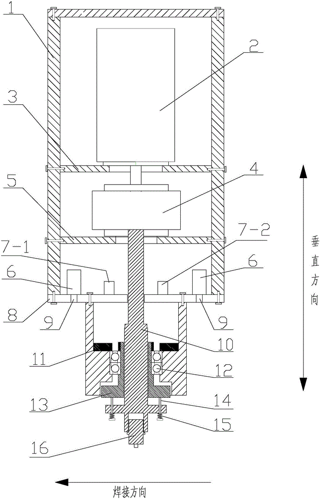
  • Friction stir welding tool with press-in depth and vibration feedback function
  • Friction stir welding tool with press-in depth and vibration feedback function

Examples


Embodiment Construction

[0016] The applicant conducted research and analysis on existing patents and papers. For example, prior art 1 proposes a friction stir welding device, but does not provide a specific method for how to measure the depression depth of the stirring head and the inclination angle of the stirring head in real time. Prior art 2 proposes a friction stir welding device. The torque motor stator is fixedly installed in the inner hole of the main shaft, which makes the whole device too bulky. In addition, there is no specific basis for the adjustment of welding parameters during the welding process. However, the technical solution using the PID algorithm has a large time lag and overshoot, and many problems will occur. In addition, none of the existing schemes addresses an important issue, that is, the deviation between the measured values ​​of pressure, vibration, and torque from the real values, and thus does not provide a solution.

[0017] Therefore, the applicant believes that it i...


PUM


Abstract

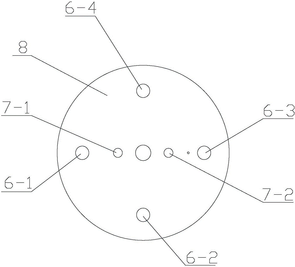
The invention discloses a friction stir welding tool with a press-in depth and vibration feedback function. The friction stir welding tool comprises a hollow welder shell, a hollow machine head shell, a third supporting frame, a first supporting frame, a second supporting frame, a main motor, a torque sensor, a central shaft, four laser ranging devices, a welding direction vibration sensor and a vertical direction vibration sensor, wherein the third supporting frame is arranged at the open end of the welder shell, the first supporting frame and the second supporting frame are arranged in the welder shell at intervals, the main motor is fixed to the first supporting frame, and the torque sensor is located on the second supporting frame and in transmission connection with the output end of the main motor; and the central shaft penetrates through the third supporting frame and the second supporting frame and is fixedly connected with the torque sensor, the four laser ranging devices are evenly arranged on the third supporting frame in the circumferential direction of the central shaft, and the welding direction vibration sensor and the vertical direction vibration sensor are arranged on the third supporting frame and symmetrical about the central shaft. According to the friction stir welding tool, the whole welding process can be monitored, and the stability and safety of welding states at every moment of the welding process are ensured; and meanwhile, vibration in the welding direction and the vertical direction is monitored, and obtained data are more reliable and real.

Description

technical field [0001] The invention relates to non-ferrous metal welding processing technology, in particular to a welding tool suitable for new friction stir welding. Background technique [0002] Since the Friction Stir Welding method was invented by the British Welding Institute, this technology can eliminate welding defects such as pores, inclusions, cracks, etc. due to its small welding deformation, small residual stress, no need for protective gas and filling materials, and no arc light, smoke and dust. , noise pollution, etc. At the same time, it can significantly reduce costs, save materials, optimize structures, and reduce the structural weight of aircraft, etc., which have attracted the attention of scientific research institutions in various countries. Because this technology has many remarkable features that other methods do not have, it will soon be used in the aerospace field, and this method is selected for the welding of the longitudinal seam of the core tan...

Claims


Application Information

Patent Timeline
IPC IPC(8): B23K20/12B23K20/26
CPCB23K20/123B23K20/26
Inventor 陈书锦周洋倪瑞洋夏晶宇王鹏浩
Owner JIANGSU UNIV OF SCI & TECH
Why Eureka
Eureka Blog
Learn More