System and method for recycling copper slag waste heat and directly reducing and extracting iron

A technology for slag waste heat and copper recovery, which is applied to furnace types, furnaces, shaft furnaces, etc. to reduce energy consumption, improve waste heat recovery rate, and reduce production costs.

Active Publication Date: 2016-11-09
NORTHEASTERN UNIV
View PDF4 Cites 12 Cited by
  • Summary
  • Abstract
  • Description
  • Claims
  • Application Information

AI Technical Summary

Problems solved by technology

[0011] Aiming at the problems existing in the existing technology, the present invention provides a system and method for recovering c

Method used


Image

  • System and method for recycling copper slag waste heat and directly reducing and extracting iron
  • System and method for recycling copper slag waste heat and directly reducing and extracting iron
  • System and method for recycling copper slag waste heat and directly reducing and extracting iron

Examples


Example Embodiment

[0042] Example 1

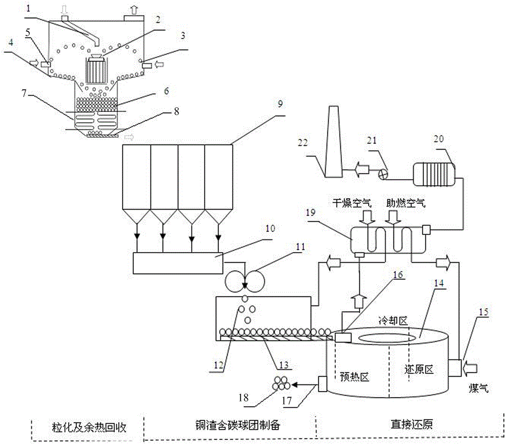
[0043] The structure of the system for recovering copper slag waste heat and directly reducing iron and raising iron in this embodiment is as follows figure 1 As shown, it consists of a slag granulation and waste heat recovery device, a copper slag carbon-containing pellet preparation device and a direct reduction device;

[0044] The slag granulation and waste heat recovery device includes a slag granulation component and a waste heat recovery component. The slag granulation component is composed of a slag slag tank 1, a centrifugal granulation device 2, a blower 5, and a slag particle collection device 4. The slag particle collection device 4 is a funnel-shaped container with a wide upper and a narrow bottom. The centrifugal granulation device 2 capable of rotating at a high speed is arranged inside the slag particle collection device 4, and the slag slag tank 1 extends from above. Inside the slag particle collection device 4, and the discharge port of the slag...

Example Embodiment

[0055] Example 2

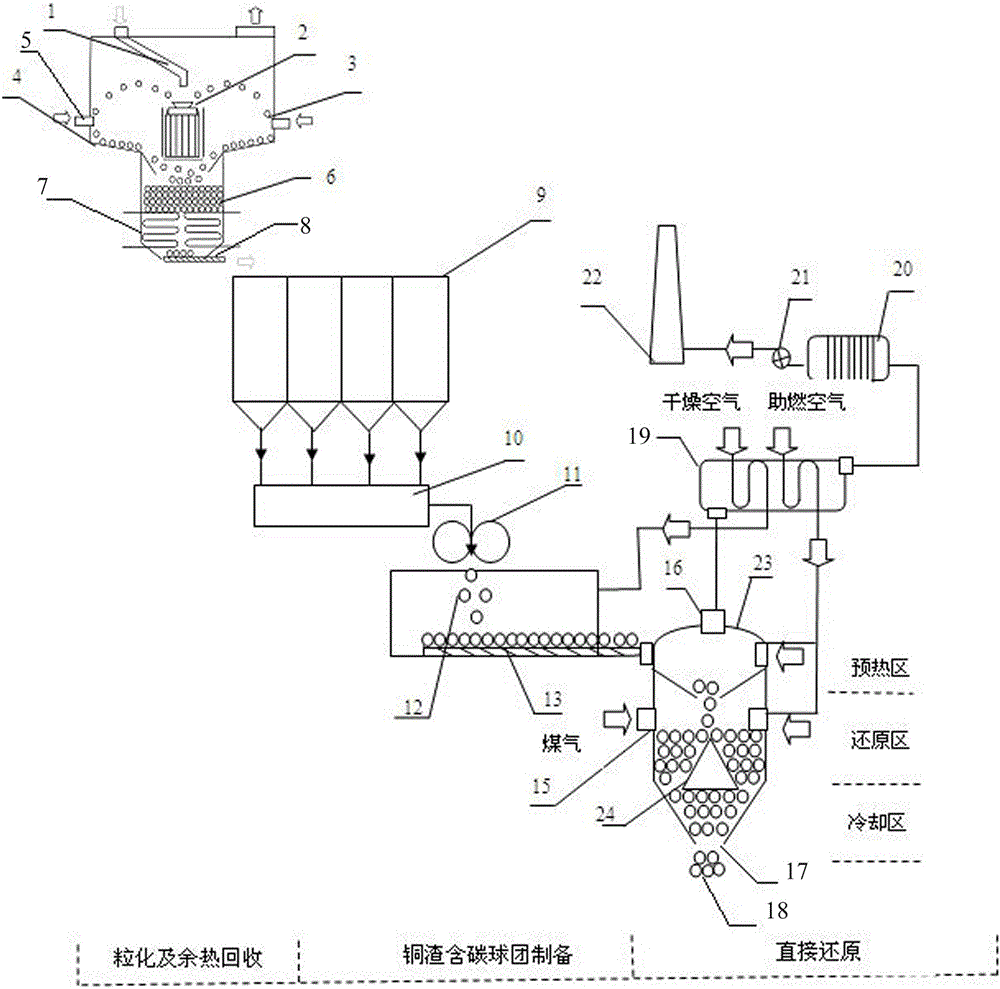
[0056] The structure of the system for recovering copper slag waste heat and directly reducing iron and raising iron in this embodiment is as follows figure 2 As shown, it consists of a slag granulation and waste heat recovery device, a copper slag carbon-containing pellet preparation device and a direct reduction device;

[0057] The slag granulation and waste heat recovery device includes a slag granulation component and a waste heat recovery component. The slag granulation component is composed of a slag slag tank 1, a centrifugal granulation device 2, a blower 5, and a slag particle collection device 4. The slag particle collection device 4 is a funnel-shaped container with a wide upper and a narrow bottom. The centrifugal granulation device 2 capable of rotating at a high speed is arranged inside the slag particle collection device 4, and the slag slag tank 1 extends from above. Inside the slag particle collection device 4, and the discharge port of the sl...


PUM

PropertyMeasurementUnit
Diameteraaaaaaaaaa

Abstract

The invention belongs to the technical field of non-ferrous metallurgy and particularly relates to a system and method for recycling copper slag waste heat and directly reducing and extracting iron. According to the system and method for recycling the copper slag waste heat and directly reducing and extracting the iron, granulated copper slag particles are directly prepared into copper slag carbon-containing particles, the ore grinding procedure is omitted, and the energy consumption in the pelleting process of pellets in the prior art is reduced; in a drying furnace, the compressive strength of dried copper slag carbon-containing pellets is improved, and a guarantee is provided for direct reducing; according to the system and method for recycling the copper slag waste heat and directly reducing and extracting the iron, by controlling the temperature of a reducing furnace, the reducing rate of the iron in copper slag is increased; and by recycling flue gas waste heat in the furnace, the waste heat recycling rate is increased, the production cost is reduced, the energy conservation and emission reduction purposes are achieved, and the problem that copper slag waste heat recycling and iron recycling are different at current is solved.

Description

technical field [0001] The invention belongs to the technical field of nonferrous metallurgy, and in particular relates to a system and method for recovering waste heat of copper slag and directly reducing and extracting iron. Background technique [0002] Copper slag is a by-product discharged during the copper smelting process, the main components are fayalite and magnetite, and the temperature of the furnace can reach 1300 °C. According to relevant statistics, the copper slag produced in my country alone is as high as 15 million tons every year. The iron content in copper slag can reach 30% to 45%, which has a high waste heat recovery value and metal recovery value. The current treatment method for copper slag is rapid cooling by water quenching, and the cooled copper slag is stored as waste slag. This treatment method not only fails to recover the high-temperature waste heat of copper slag, but also wastes water resources, and the iron in copper slag cannot be recovere...

Claims


Application Information

Patent Timeline
IPC IPC(8): C21B13/02C21B13/10C22B1/24C22B1/243C22B1/245
CPCC21B13/02C21B13/10C21B2200/00C22B1/24C22B1/2406C22B1/243C22B1/245
Inventor 于庆波左宗良王拓闫子文秦勤
Owner NORTHEASTERN UNIV
Why Eureka
Try Eureka