Pressing-down type crimping machine for short fiber production line
A production line and crimping machine technology, applied in non-polymer organic compound adhesives, textiles and papermaking, non-polymer adhesive additives, etc., can solve the problem of not meeting the requirements of fiber crimping process, short service cycle and increasing production costs, etc. problems, to achieve the effect of reducing the cumulative installation error, reducing maintenance costs, and not easy to collide
- Summary
- Abstract
- Description
- Claims
- Application Information
AI Technical Summary
Problems solved by technology
Method used
Image
Examples
Embodiment 1
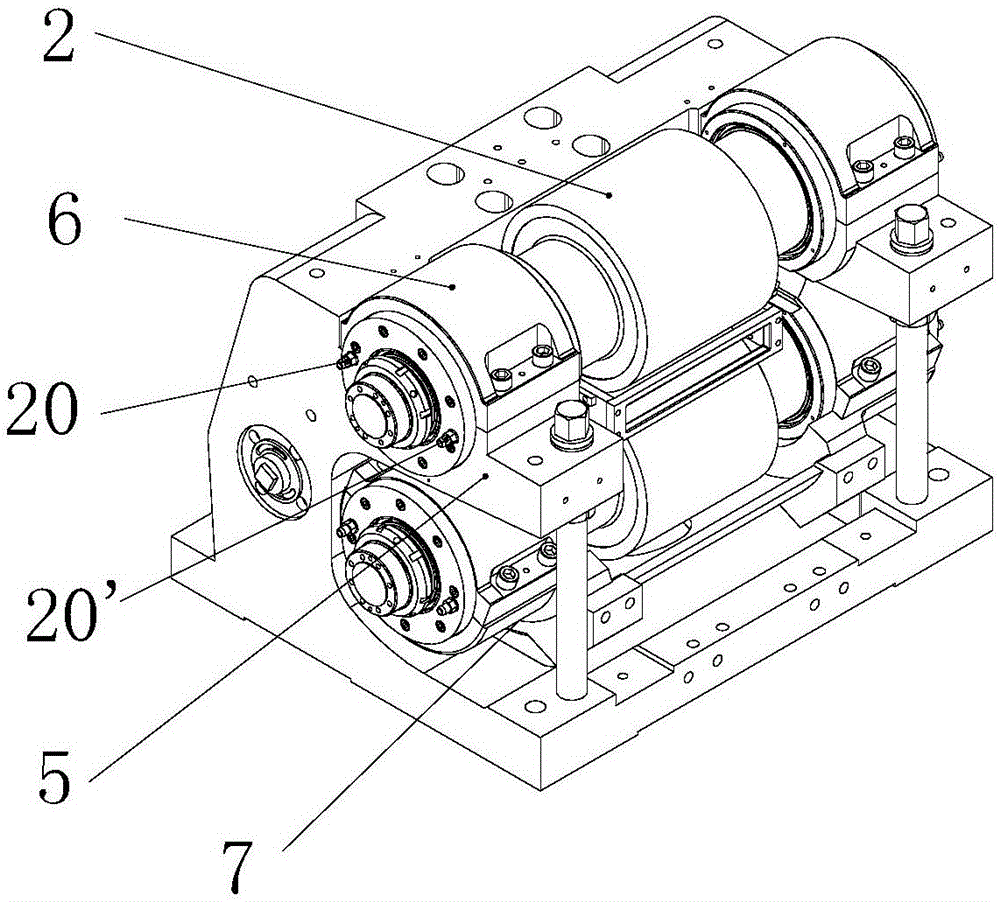
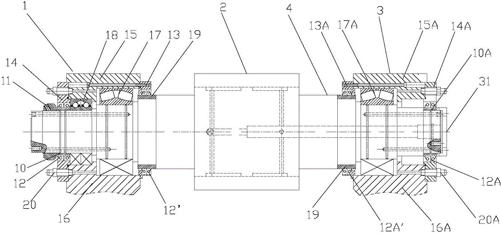
[0016] A kind of down-pressing crimping machine for staple fiber production line provided by this embodiment, the structure is as follows: figure 1 As shown, it includes a crimping roller, a machine base 5 and a lower rocker arm 7, and a pair of crimping rollers rotating together are installed on the machine base and the lower rocker arm. The roll includes a curling roller 2 and curling rollers 4 arranged on both sides of the curling roller. The curling rollers at both ends of the curling roller are connected with the base and the lower rocker arm through a rotating mechanism. The rotating mechanism is composed of a power input transmission mechanism 1 and a heating The transmission mechanism at the input end consists of 3; the transmission mechanism at the power input end includes an inner flange 13, an outer flange 14, a bearing bush cover 15, a frame bearing bush 16, a radial load bearing 17 and an axial load bearing arranged at the end of the curling roller shaft. 18. The ...
Embodiment 2
[0020] This example provides a down-pressing crimping machine for a staple fiber production line. On the basis of Example 1, a composite film is pasted on the surface of the crimping roller, so that the chemical fiber can be heated evenly and prevent the chemical fiber from sticking to the On the curling roller, it is wear-resistant and has a long service life.
[0021] The composite film includes a PTFE film, one side of the PTFE film is coated with a cross-linked adhesive, and the other side of the PTFE film is sprayed with a nano solution, and the composite film is bonded to the curling roller through the cross-linked adhesive;
[0022]The mass percentage components of the cross-linked adhesive are: 4-methylcyclohexyl isocyanate: 35%, urethane: 9%, α-linolenic acid: 6%, ethoxylated bisphenol A dimethacrylate: 7%, Trimethylolpropane Trimethacrylate: 2%, Benzoyl Peroxide: 3%, Butyl Acrylate: 4%, Crosslinked Acrylate Emulsion: 5%, 2-Hydroxy-1,2 - Diphenyl ethyl ketone: 0.7%, ...
Embodiment 3
[0025] This example provides a down-pressing crimping machine for a staple fiber production line. On the basis of Example 1, a composite film is pasted on the surface of the crimping roller, so that the chemical fiber can be heated evenly and prevent the chemical fiber from sticking to the On the curling roller, it is wear-resistant and has a long service life.
[0026] The composite film includes a PTFE film, one side of the PTFE film is coated with a cross-linked adhesive, and the other side of the PTFE film is sprayed with a nano solution, and the composite film is bonded to the curling roller through the cross-linked adhesive;
[0027] The mass percentage components of the cross-linked adhesive are: 4-methylcyclohexyl isocyanate: 36%, urethane: 10%, α-linolenic acid: 7%, ethoxylated bisphenol A dimethacrylate: 8%, Trimethylolpropane Trimethacrylate: 3%, Benzoyl Peroxide: 4%, Butyl Acrylate: 5%, Crosslinked Acrylate Emulsion: 6%, 2-Hydroxy-1,2 -Diphenyl ethyl ketone: 0.8%,...
PUM
 Abstract
Description
Claims
Application Information
 - R&D
- Intellectual Property
- Life Sciences
- Materials
- Tech Scout
- Unparalleled Data Quality
- Higher Quality Content
- 60% Fewer Hallucinations
Browse by: Latest US Patents, China's latest patents, Technical Efficacy Thesaurus, Application Domain, Technology Topic, Popular Technical Reports.
© 2025 PatSnap. All rights reserved.Legal|Privacy policy|Modern Slavery Act Transparency Statement|Sitemap|About US| Contact US: help@patsnap.com


