
A system for coupling and drying slurry thermal insulation materials by using waste heat of flue gas

A technology for thermal insulation materials and flue gas waste heat, which is applied in the direction of static material dryers, solid material drying, local agitation dryers, etc. It can solve the problems of poor thermal insulation effect, little use value, and huge heat loss, etc. , to achieve the effect of improving heat conversion efficiency, rapid and convenient application, and solving application bottlenecks

Active Publication Date: 2018-07-17
山东大千热力工程有限责任公司
View PDF5 Cites 0 Cited by
  • Summary
  • Abstract
  • Description
  • Claims
  • Application Information

AI Technical Summary

Problems solved by technology

[0004] First, for the heat loss of flue gas, the current method mainly uses the gradient heat exchange of flue gas to preheat hot water or coal to improve the combustion efficiency of the boiler, but even after a series of comprehensive utilization in the existing technology, the exhausted flue gas The gas temperature is still above 120 degrees Celsius. For units that generate a large amount of smoke for a long time, the heat loss is huge
Taking the current large-scale boiler (above 150 MW single-unit capacity) as an example, its thermal efficiency has reached over 90%, but its exhaust gas temperature is also above 120 degrees Celsius, and the flue gas in this temperature range has not been used much in the original system. value, but it does take away a lot of calories
[0005] In the second aspect, the heat loss of thermal equipment and pipelines in thermal power enterprises is considerable, mainly due to the heat loss from high-temperature thermal equipment and pipelines to the external environment. For a 1000MW thermal power plant, even if it is thermally insulated according to national standards, one day The heat loss is also equivalent to an extra loss of 120 tons of standard coal. If the thermal insulation effect is not good, the heat loss will increase several times
The above-mentioned bottleneck problem in construction and drying and forming has largely restricted the application and promotion of slurry-like thermal insulation materials with excellent performance, and also directly hindered the replacement of thermal equipment and pipeline insulation materials in thermal power enterprises, resulting in the current thermal power enterprises thermal equipment, Pipeline insulation materials are outdated and heat loss is still relatively serious

Method used


Image

  • A system for coupling and drying slurry thermal insulation materials by using waste heat of flue gas
  • A system for coupling and drying slurry thermal insulation materials by using waste heat of flue gas

Examples


Embodiment Construction

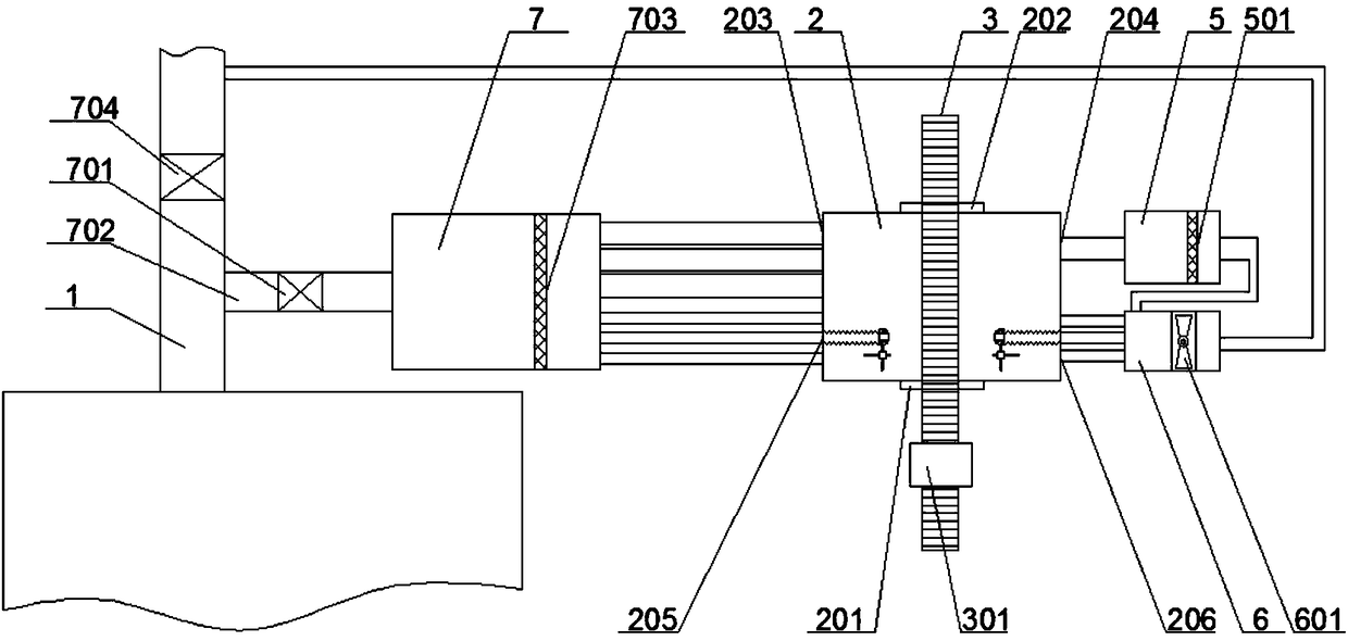
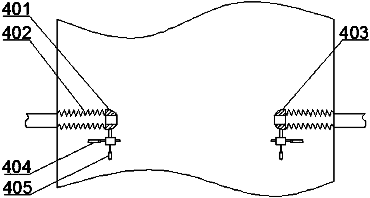
[0020] The invention relates to a system for coupling and drying slurry-like thermal insulation materials by using waste heat of flue gas, which includes a flue gas conveying mechanism and a heat recovery mechanism that communicate with a flue 1 and are sequentially connected front and rear, and the heat recovery mechanism includes a drying unit , a dust removal unit and a return air unit, the drying unit includes a drying cavity 2 with an inlet door 201 and an outlet door 202 on both sides, and a first air inlet 203 and a second air inlet 205 are provided at the front end of the drying unit Connected with the flue gas conveying mechanism, the rear end is provided with a first air outlet 204 and a second air outlet 206 connected with the dust removal unit and the return air unit, and a pipeline internal heating system is arranged between the second air inlet 205 and the second air outlet 206 , the drying unit is provided with a conveying track 3 with a carrying trolley 301 that...


PUM


Abstract

The invention relates to a system for utilizing flue gas residual heat for carrying out coupled drying on a slurry heat preservation material, and belongs to the technical field of energy utilization. The drying system comprises a drying unit connected to the rear end of a flue gas conveying mechanism, a dust removal unit and an air returning unit; the drying unit utilizes flue gas heat for drying the slurry heat preservation material on thermal equipment, a pipeline interior through-flow heating system is further arranged in the drying unit and is used for introducing high-temperature flue gas into the thermal equipment or a pipeline, and therefore drying of the slurry heat preservation material is strengthened; and the drying system can recycle heat of flue gas of a thermal power plant, waste of heat is avoided, the aim that the flue gas heat is used for drying the slurry heat preservation material of the thermal equipment and the pipeline of the equipment can be achieved, the bottleneck problem in the application and popularization process of the slurry heat preservation material is solved, the improvement of the heat preservation effect of the thermal equipment is promoted, and the emissions of heat of the thermal equipment and heat in the conveying pipeline of the equipment are greatly reduced.

Description

technical field [0001] The invention belongs to the technical field of energy utilization, and in particular relates to a system for coupling and drying slurry-like thermal insulation materials by using waste heat of flue gas. Background technique [0002] A thermal power plant is a production unit that produces steam and electricity by burning coal, natural gas, combustible biomass and other fuels. In the process of energy conversion, there will inevitably be heat loss, and the smaller the heat loss of the entire device, the less heat or electricity it produces. The higher the efficiency, the higher the current pressure on energy and the environment, the requirements for energy conversion efficiency and emission indicators of thermal power plants are also increasing. [0003] The heat loss of the thermal power plant mainly comes from two aspects, the heat loss of the flue gas and the heat loss of the thermal equipment pipeline. [0004] First, for the heat loss of flue gas...

Claims


Application Information

Patent Timeline
Patent Type & Authority Patents(China)
IPC IPC(8): F26B23/10F27D17/00F26B9/06F26B25/02
CPCF26B9/06F26B23/10F26B25/02F27D17/004Y02P10/25Y02P70/10
Inventor 方民刘永平
Owner 山东大千热力工程有限责任公司
Learn More