Miniature ultraviolet-visible/infrared nondestructive test spectrometer

An infrared non-destructive testing and spectrometer technology, applied in the field of optical instruments, can solve problems such as large measurement error, unsatisfactory spectral resolution, and increased system complexity, achieving good anti-interference and stability, ideal spectral resolution, and convenience. The effect of promotion

Inactive Publication Date: 2016-11-09
刘天军
View PDF4 Cites 4 Cited by
  • Summary
  • Abstract
  • Description
  • Claims
  • Application Information

AI Technical Summary

Problems solved by technology

[0006] First, the spectral resolution is not ideal
In the optical path, the divergent light emitted by the polychromatic light source is difficult to focus and image in a short distance after being diffracted by the plane transmission grating, so the spectral overlap is serious and the spectral resolution is not ideal
[0007] Second, the optical path is complex and the anti-interference is poor
Some optical components in the light splitting path, such as reflective micromirrors, are particularly sensitive to ambient temperature, causing the accuracy and stability of the spectrometer system to change with the ambient temperature. Using a complex temperature control system to control the temperature of these components will increase the system temperature. complexity, cost
At the same time, the complex optical path system has high requirements on the position of optical components. Once the optical components are misaligned due to physical factors such as vibrati

Method used


Image

  • Miniature ultraviolet-visible/infrared nondestructive test spectrometer
  • Miniature ultraviolet-visible/infrared nondestructive test spectrometer
  • Miniature ultraviolet-visible/infrared nondestructive test spectrometer

Examples


Embodiment 1

[0032] Example 1 Reflective multi-wavelength miniature ultraviolet-visible / infrared non-destructive testing spectrometer

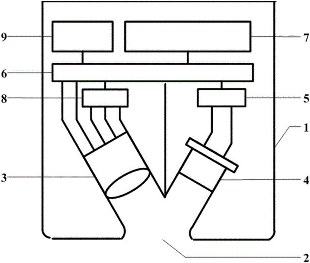
[0033] The light source 3, photoelectric sensor 4, circuit system and power supply 9 of a miniature ultraviolet-visible / infrared nondestructive testing spectrometer are all installed in the casing 1 (see figure 1 , 3 -4). The light source 3, the irradiation center point, and the photoelectric sensor 4 are located on the same plane, and the angles between the light output path of the light source 3, the detection path of the photoelectric sensor 4, and the normal line of the irradiation center point are equal to ensure that the reflected light enters the photoelectric sensor 4 to the maximum extent. .

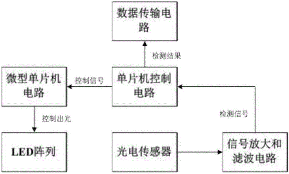
[0034] The light source 3 includes pins, tube sockets, aluminum substrates, micro-single-chip microcomputer circuits, LED arrays, light guides and light guide tubes (see Figure 5 ). The pins include two voltage supply pins, common ground pins, data tran...

Embodiment 2

[0040] Example 2 Reflective dual-wavelength miniature ultraviolet-visible / infrared nondestructive testing spectrometer

[0041] The light source 3, photoelectric sensor 4, circuit system and power supply 9 of a miniature ultraviolet-visible / infrared nondestructive testing spectrometer are all installed in the casing 1 (see Figure 3-4 ). The light source 3, the irradiation center point, and the photoelectric sensor 4 are located on the same plane, and the angles between the light output path of the light source 3, the detection path of the photoelectric sensor 4, and the normal line of the irradiation center point are equal to ensure that the reflected light enters the photoelectric sensor 4 to the maximum extent. .

[0042] The light source 3 includes pins, tube sockets, aluminum substrates, micro-single-chip microcomputer circuits, LED arrays, light guides and light guide tubes (see Figure 5 ). The pins include two voltage supply pins, common ground pins, data transmissi...

Embodiment 3

[0048] Example 3 Transmissive multi-wavelength miniature ultraviolet-visible / infrared non-destructive testing spectrometer

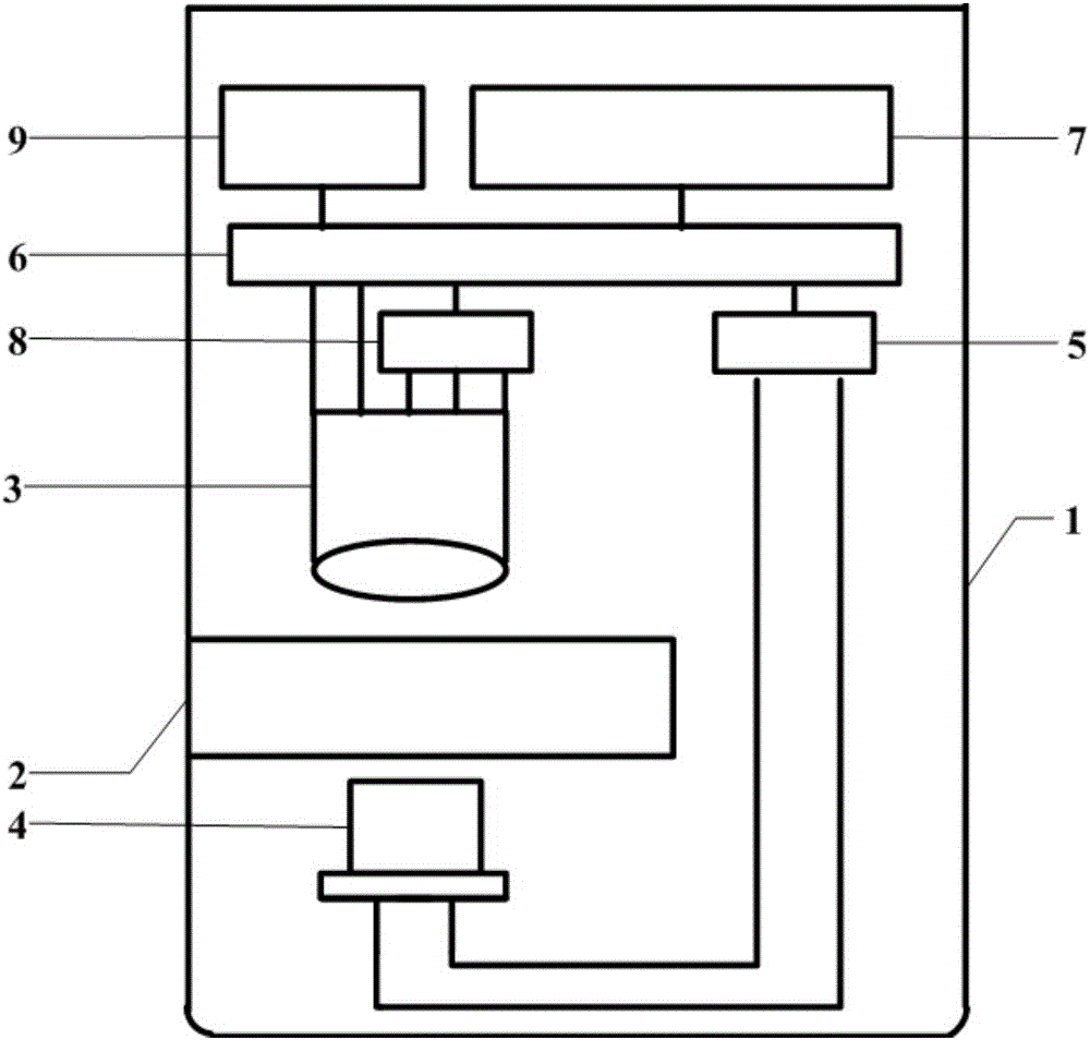
[0049] The light source 3, photoelectric sensor 4, circuit system and power supply 9 of a miniature ultraviolet-visible / infrared nondestructive testing spectrometer are all installed in the casing 1 (see Figure 2-4 ). The light source 3, the central point of irradiation and the photoelectric sensor 4 are located on the same plane, and the light output path of the light source 3, the detection path of the photoelectric sensor 4, and the central point of irradiation are on the same straight line to ensure that the transmitted light enters the photoelectric sensor 4 to the maximum extent.

[0050] The light source 3 includes pins, tube sockets, aluminum substrates, micro-single-chip microcomputer circuits, LED arrays, light guides and light guide tubes (see Figure 5 ). The pins include two voltage supply pins, common ground pins, data transmission pins ...


PUM


Abstract

The invention discloses a miniature ultraviolet-visible/infrared nondestructive test spectrometer. The nondestructive test spectrometer comprises a light source, a photoelectric sensor, a circuit system, a housing and a power source. The light source comprises a base pin, a base, an aluminum substrate, a minisize single-chip microcomputer circuit, a LED array, an optical conductor and a light guide cylinder; the photoelectric sensor is an ultraviolet/infrared silicon photodiode; the circuit system comprises a single-chip microcomputer control circuit, a power amplifier circuit, a signal amplification and filter circuit, and a data transmission circuit; the housing is the cylinder with a light source slot, a power source socket, a communication socket, and a separating layer; and the power source is the DC source. The miniature ultraviolet-visible/infrared nondestructive test spectrometer can be used for determining the ultraviolet-visible/infrared transmission reflection absorption spectrum of one or more specific target substances, and has the advantages of small whole machine volume, light weight, and low cost, is suitable for on-site detection and is convenient for popularization, spectrum resolution is ideal, and the anti-interference performance and the stability of the system are good.

Description

technical field [0001] The invention belongs to the field of optical instruments, and specifically relates to a miniature ultraviolet-visible / infrared non-destructive testing spectrometer and its application, in particular to a light source, a photoelectric sensor, a circuit system, a casing and a power supply, which are used for non-destructive testing of one or more specific spectrometers. Device for UV-Vis / IR spectroscopy of target substances. Background technique [0002] Spectral detection is an emerging detection technology for qualitative or quantitative analysis by measuring the intensity of transmitted or reflected light of target substances in the ultraviolet-visible and infrared regions. The spectrometer developed based on this technology can be used in food and environmental detection, chemical composition quantification, electromagnetic radiation analysis and other fields. The traditional spectrometer is composed of many optical, electrical and mechanical syste...

Claims


Application Information

Patent Timeline
IPC IPC(8): G01N21/27
CPCG01N21/27G01N2021/1742
Inventor 刘天军董晓曦洪阁
Owner 刘天军
Why Eureka
Try Eureka