
High precision wide frequency domain frequency measuring system and frequency measuring method

A technology of frequency measurement and wide frequency domain, which is applied in the field of signal measurement, can solve the problems of affecting accuracy, different accuracy, and low cost, and achieve the effects of ensuring measurement accuracy, easy expansion and application, and convenient operation

Inactive Publication Date: 2016-11-09
SHENZHEN INST OF ADVANCED TECH
View PDF8 Cites 12 Cited by
  • Summary
  • Abstract
  • Description
  • Claims
  • Application Information

AI Technical Summary

Problems solved by technology

[0004] Usually, because the components are affected by aging, temperature, working frequency and working voltage, too high or too low input signal frequency will affect the accuracy and stability of the output of the waveform shaping circuit and frequency division circuit, so the frequency counting will also A certain error will be generated, which directly affects the frequency measurement accuracy of the frequency meter. At present, most frequency meters do not consider the dynamic parameter compensation of frequency measurement, which leads to the difference in the measurement accuracy of high frequency and low frequency signals.
To realize the frequency measurement of conventional periodic signals, a shaping circuit is first required to convert non-rectangular wave signal sources (such as triangular waves, sawtooth waves, sine waves, etc.) The shaping circuit is fully capable of shaping low-frequency signals, but it is often difficult to adapt to shaping high-frequency signals. It has a poor effect on frequency shaping at the MHZ level, because the waveform is severely distorted and becomes less than a standard rectangular wave, which affects the accuracy of subsequent frequency measurements.
Chinese patent CN103472300A introduces a simple technical frequency meter, including a logic circuit composed of an integrated circuit CD4017, a time base circuit composed of a 555 timer, a CD40110 integrated circuit and a digital tube. The frequency measurement scheme is all implemented by hardware without micro-processing Software control of the device, the cost is low, but because there is no waveform shaping circuit, the frequency of non-rectangular waves (such as sine waves, triangle waves, etc.) cannot be measured
The frequency meter mentioned in Chinese patent CN103499738A includes modules such as shaping circuit, frequency division circuit, and microprocessor, but the frequency measurement range of this scheme is only 0HZ-9999HZ, the frequency band is very narrow, and the stability and accuracy are difficult to guarantee
[0005] In order to achieve high-precision frequency measurement, a high-speed processor is often required to provide a high-precision timer as a time base signal and a high-precision counter to count pulses, but the corresponding processor cost and power consumption are often relatively high, and for High-frequency signals are still difficult to measure without a suitable frequency division circuit. Chinese patent CN102749508A introduces a frequency measurement device and method. The device includes a central processing unit and a filter circuit and a timer connected to the central processing unit; the filter circuit is used to convert the sine wave The electrical signal is converted into a square wave electrical signal with the same cycle as the sine wave electrical signal; the timer is used to record the moment when the square wave electrical signal is reversed; the central processing unit is used to receive the square wave electrical signal output by the filter circuit, and read the time recorded by the timer. The moment of occurrence and the inversion period of the square wave electrical signal are determined, and the frequency of the sine wave electrical signal is determined according to the inversion period, but the system cannot measure high-frequency signals because there is no frequency division circuit

Method used


Image

  • High precision wide frequency domain frequency measuring system and frequency measuring method
  • High precision wide frequency domain frequency measuring system and frequency measuring method
  • High precision wide frequency domain frequency measuring system and frequency measuring method

Examples


Embodiment Construction

[0023] The present invention will be described in more detail below in conjunction with the accompanying drawings and embodiments.

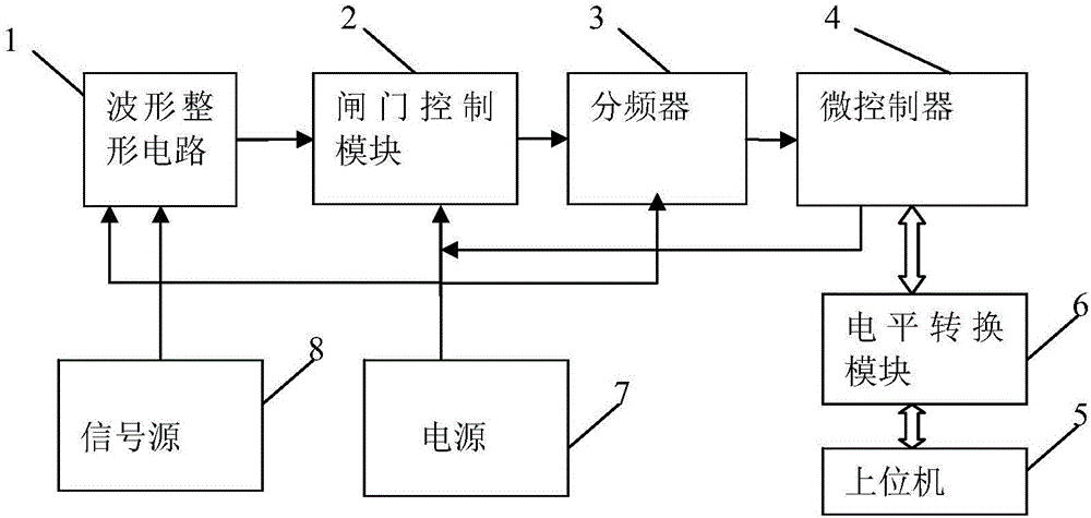
[0024] The invention discloses a high-precision wide-frequency domain frequency measurement system, such as figure 1 As shown, it includes:

[0025] A waveform shaping circuit 1, whose input terminal is connected to the signal source 8, and the waveform shaping circuit 1 is used for shaping and transforming the waveform signal output by the signal source 8 into a rectangular wave signal;

[0026] A gate control module 2, the input end of which is connected to the output end of the waveform shaping circuit 2, and the gate control module 2 is used to execute a control command to control the on / off of the rectangular wave signal;

[0027] A frequency divider 3, the input end of which is connected to the output end of the gate control module 2, and the frequency divider 3 is used to output the pulse signal after the frequency division processing of ...


PUM


Abstract

The invention discloses a high precision wide frequency domain frequency measuring system The high precision wide frequency domain frequency measuring system comprises a waveform shaping circuit, the input end of which is connected with a signal source; a gate control module, which is used to execute a control instruction to control connection / disconnection of a rectangular wave signal; a frequency divider, which is used to output a pulse signal after carrying out the frequency division processing of the rectangular wave signal; a microcontroller, which is used to transmit the control instruction to a gate control module, is used to count the pulse signal output by the frequency divider, is used to calculate signal frequency data, and is used to calibrate the signal frequency data according to a frequency measurement correction parameter; an upper computer, which is connected with the microcontroller, is used to transmit the frequency measurement correction parameter to the microcontroller, and is used to receive the calibrated signal frequency data uploaded by the microcontroller. The high precision wide frequency domain frequency measuring system and a frequency measuring method are advantageous in that the high precision wide frequency domain frequency measurement is realized, the structure is simple, the operation is convenient, the cost is low, the expansion is easy, and the use is stable and reliable.

Description

technical field [0001] The invention relates to the technical field of signal measurement, in particular to a high-precision wide-frequency domain frequency measurement system and a frequency measurement method. Background technique [0002] In the field of signal measurement technology, frequency measurement is a very common concept. Frequency is the reciprocal of the signal period. The frequency meter is mainly composed of four parts: time base circuit, input circuit, counting display circuit and control circuit. In traditional manufacturing enterprises, frequency meters are widely used in production testing of production lines. The frequency meter can quickly capture the change of the output frequency of the crystal oscillator. By using the frequency meter, the user can quickly find faulty crystal oscillator products and ensure product quality. In the metrology laboratory, the frequency meter is used for various electronic measurements Calibrate the local oscillator of ...

Claims


Application Information

Patent Timeline
IPC IPC(8): G01R23/10
CPCG01R23/10
Inventor 宁运琨赵国如谢高生
Owner SHENZHEN INST OF ADVANCED TECH
Learn More