Rivet for friction-self piercing riveting (F-SPR) and F-SPR connecting system thereof

A technology of riveting and welding connection and rivets, which is applied in the direction of connecting components, welding equipment, screws, etc., can solve the problems of poor stability, misalignment of rivet axis and rotation axis, etc., and achieve the effect of reducing rivet weight and ensuring rotation stability

Active Publication Date: 2016-11-16
SHANGHAI JIAO TONG UNIV
View PDF6 Cites 38 Cited by
  • Summary
  • Abstract
  • Description
  • Claims
  • Application Information

AI Technical Summary

Problems solved by technology

[0006] Aiming at the above-mentioned deficiencies in the prior art, the present invention proposes a rivet for self-piercing friction riveting welding and its connection system for self-piercing friction riveting welding. The joint use of the rivet and the connecting system can improve the performance of the rivet in the process of self-piercing friction riveting welding. Excellent driving stiffness and positioning accuracy, solve the problems of poor stability during high-speed rotation of semi-hollow rivets and misalignment of rivet axis and rotation axis, reduce joint failure probability, avoid gaps between rivets and plates, and ensure self-piercing friction riveting welding process reliability

Method used


Image

  • Rivet for friction-self piercing riveting (F-SPR) and F-SPR connecting system thereof
  • Rivet for friction-self piercing riveting (F-SPR) and F-SPR connecting system thereof
  • Rivet for friction-self piercing riveting (F-SPR) and F-SPR connecting system thereof

Examples


Embodiment 1

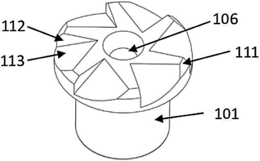
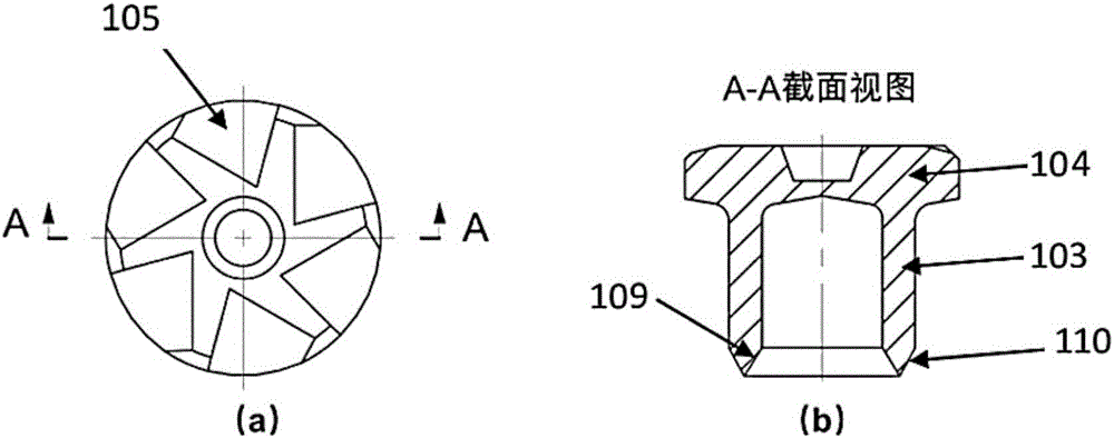
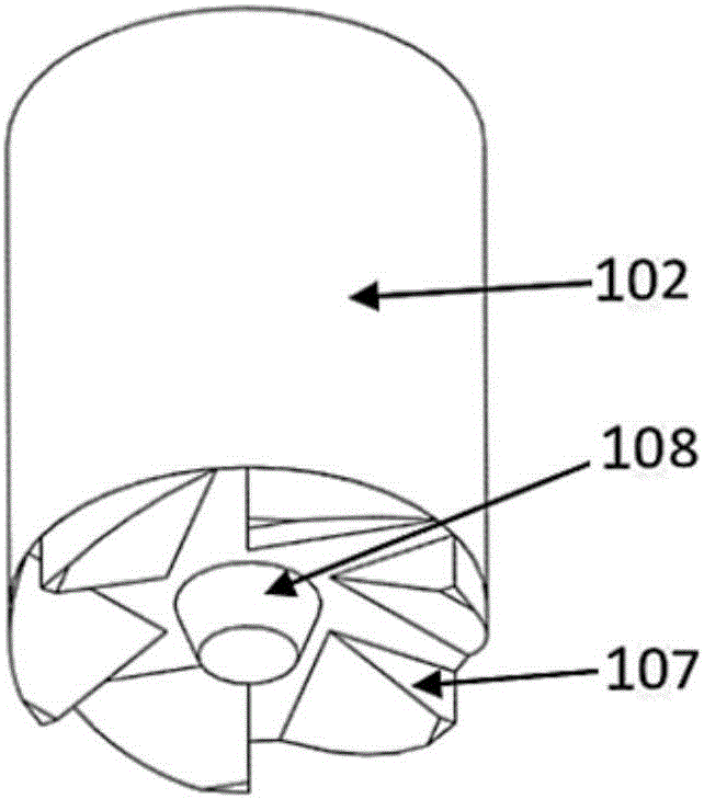
[0053] Such as Figure 1-Figure 2 As shown, this embodiment relates to a rivet 101 for self-piercing friction rivet welding, including: a semi-hollow rivet body 103 and a rivet cover 104 with six wedge-shaped notches 105 and positioning grooves 106 .

[0054] The inner diameter of the semi-hollow rivet body 103 is 4mm, the outer diameter is 6mm, and the depth is 5mm.

[0055] The diameter of the rivet cover 104 is 8mm and the height is 2mm.

[0056] The apex 109 of the wedge-shaped cone angle 110 at the bottom of the semi-tubular rivet body 103 is located between the inner wall and the outer wall, the radial distance from the inner wall is 0.4mm, and the radial distance from the outer wall is 0.6mm.

[0057] The upper edge of the rivet cover 104 is provided with a truncated cone 111 for easy loading and unloading, and the cone angle is 60°.

[0058] The six wedge-shaped notches 105 are evenly distributed on the edge of the rivet cover 104 in the circumferential direction, an...

Embodiment 2

[0077] The apex of the wedge-shaped cone angle at the bottom end of the semi-tubular rivet body 103 coincides with the outer wall.

[0078] Such as Figure 7 As shown in (a), the plate 14 in this embodiment is: aluminum alloy AA6061-T6+magnesium alloy AZ31B; the matching thickness of the plate is: 1.2mm+1.6mm.

[0079] The rivet 101 described in this embodiment, the driving rod 102 and the mold 15 with a protrusion 16 in the middle together realize the self-piercing friction rivet welding connection of the plate 14 .

[0080] Other implementation modes of this embodiment are the same as Embodiment 1.

[0081] After the self-piercing friction rivet welding process in this embodiment is over, the relative positional relationship of the rivet 101, the drive rod 102, the plate 14 and the middle belt convex die 15 is as follows Figure 7 As shown in (d), the finally obtained self-piercing friction riveting joint is as follows Figure 7 (e) shown.

[0082] Compared with the prio...

Embodiment 3

[0084] Such as Figure 8 As shown in (a), the plate 14 in this embodiment is: aluminum alloy AA6061-T6+cast aluminum Aural-2; the thickness of the plate is matched: 2mm+3mm.

[0085] The rivet 101 described in this embodiment, the driving rod 102 and the mold 15 with a flat-bottomed concave structure 17 in the middle together realize the self-piercing friction riveting connection of the plate 14 .

[0086] Other implementation modes of this embodiment are the same as Embodiment 2.

[0087] After the self-piercing friction rivet welding process in this embodiment ends, the relative positional relationship of the rivet 101, the drive rod 102, the plate 14 and the flat-bottom die 15 is as follows Figure 8 As shown in (d), the finally obtained self-piercing friction riveting joint is as follows Figure 8 (e) shown.


PUM

PropertyMeasurementUnit
depthaaaaaaaaaa
diameteraaaaaaaaaa
heightaaaaaaaaaa

Abstract

The invention discloses a rivet for friction-self piercing riveting (F-SPR) and an F-SPR connecting system thereof. The rivet comprises a semi-hollow rivet body and a rivet cap, wherein the lower surface of the rivet cap is connected with the semi-hollow rivet body; a wedge-shaped taper corner is arranged at the bottom end of the semi-hollow rivet body; chamfers for assembly and disassembly and a rotating driving structure are arranged on the edge of the upper end of the rivet cap; a locating structure is arranged in the center of the rivet cap; the rotating driving structure is a directed concave surface or a directed convex surface in central symmetry; and the locating structure is a convex surface or a concave surface in central symmetry and mirror symmetry. When the rivet is matched with a driving system for utilization, the driving rigidity and locating accuracy of the rivet during the F-SPR process can be improved, the problems that during the high-speed rotation process of the semi-hollow rivet, the stability is poor and the rivet axis and the rotation axis do not overlap are solved, the probability that a connector loses efficacy is reduced, the problem that a clearance is formed between the rivet and a panel is avoided, and the technological reliability of an F-SPR technology when connecting steel, aluminum, magnesium materials, composites and heterogeneous materials is guaranteed.

Description

technical field [0001] The invention relates to a technology in the field of automobile plate connection, in particular to a rivet for self-piercing friction riveting and its self-piercing friction riveting connection system. Background technique [0002] With the development trend of lightweight automobile body, high-strength steel, aluminum alloy, magnesium alloy and other light alloys and composite materials are being more and more widely used. However, light alloys such as aluminum and magnesium are difficult to use in traditional resistance spot welding due to their strong oxidation ability, small resistivity, large thermal conductivity, specific heat capacity and linear expansion coefficient, and easy formation of pores. to connect. Composite materials and plastics cannot be connected by soldering at all because they do not conduct electricity. [0003] Aiming at the connection problem of the above-mentioned lightweight materials, self-piercing riveting (Self-Piercin...

Claims


Application Information

Patent Timeline
Patent Type & Authority Applications(China)
IPC IPC(8): B23P23/04
CPCB23P23/04B21J15/025B21J15/12B23K20/12B21K25/005B21J5/063B21J15/027F16B19/086
Inventor 李永兵马运五楼铭林忠钦
Owner SHANGHAI JIAO TONG UNIV
Why Eureka
Try Eureka