Method for removing impurities in metallurgic silicon
A technology of metallurgical grade silicon and impurities, applied in the field of silicon purification, to achieve the effect of less acid consumption
- Summary
- Abstract
- Description
- Claims
- Application Information
AI Technical Summary
Problems solved by technology
Method used
Image

Examples
Embodiment 1
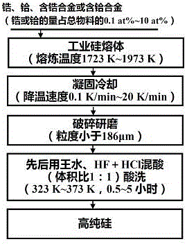
[0022] Such as figure 1 As shown, a method for removing impurities in metallurgical grade silicon, the specific steps are as follows:
[0023] (1) Add Zr to industrial silicon (the amount of added Zr accounts for 10% of the total molar number of materials) and put it into a high-purity dense graphite crucible for melting. The melting temperature is 1723K, and the melting atmosphere is argon protective gas;
[0024] (2) Cool down the completely melted silicon melt in step (1) to room temperature at a rate of 20K / min;
[0025] (3) Grinding the silicon obtained in step (2) into silicon powder smaller than 186 μm;
[0026] (4) Pickling the silicon powder obtained in step (3) with aqua regia, HF+HCl mixed acid (the volume ratio of HF and HCl is 1:1) to obtain high-purity silicon, the pickling temperature is 323K, and the pickling time is 5h.
[0027] After step (4), the content changes of main impurity elements in silicon are shown in Table 1, where the added Zr is reduced from ...
Embodiment 2
[0032] Such as figure 1 As shown, a method for removing impurities in metallurgical grade silicon, the specific steps are as follows:
[0033] (1) Add Si-30at%Zr alloy to industrial silicon (the amount of Zr added accounts for 0.1% of the total molar number of materials) and put it into a high-purity dense graphite crucible for melting. The melting temperature is 1973 K and the melting atmosphere is Argon protective gas;
[0034] (2) Cool down the completely melted silicon melt in step (1) to room temperature at a rate of 0.1K / min;
[0035] (3) Grinding the silicon obtained in step (2) into silicon powder smaller than 186 μm;
[0036] (4) The silicon powder obtained in step (3) was pickled successively with aqua regia, HF+HCl mixed acid (the volume ratio of HF and HCl was 1:1) to obtain high-purity silicon. The pickling temperature was 353 K, and the pickling time was 0.5h.
[0037] After step (4), the content changes of main impurity elements in silicon are shown in Table...
Embodiment 3
[0042] Such as figure 1 As shown, a method for removing impurities in metallurgical grade silicon, the specific steps are as follows:
[0043] (1) Add Hf to industrial silicon (the amount of added Hf accounts for 10% of the total molar number of materials) and put it into a high-purity dense graphite crucible for melting. The melting temperature is 1803K, and the melting atmosphere is argon protective gas;
[0044] (2) Cool down the completely melted silicon melt in step (1) to room temperature at a speed of 10K / min;
[0045] (3) Grinding the silicon obtained in step (2) into silicon powder smaller than 186 μm;
[0046] (4) The silicon powder obtained in step (3) was pickled successively with aqua regia, HF+HCl mixed acid (the volume ratio of HF and HCl was 1:1) to obtain high-purity silicon. The pickling temperature was 333 K, and the pickling time was for 3h.
[0047] After step (4), the content changes of main impurity elements in silicon are shown in Table 3, where the ...
PUM
 Abstract
Description
Claims
Application Information
 - R&D
- Intellectual Property
- Life Sciences
- Materials
- Tech Scout
- Unparalleled Data Quality
- Higher Quality Content
- 60% Fewer Hallucinations
Browse by: Latest US Patents, China's latest patents, Technical Efficacy Thesaurus, Application Domain, Technology Topic, Popular Technical Reports.
© 2025 PatSnap. All rights reserved.Legal|Privacy policy|Modern Slavery Act Transparency Statement|Sitemap|About US| Contact US: help@patsnap.com