
Gradient combined bed gasification system

A gasification system and combined bed technology, which is applied in gasification process, granular/powder fuel gasification, and production of combustible gas, etc., can solve the problems of low processing requirements, low reaction temperature, high carbon conversion rate, and achieve high carbon Conversion rate, the effect of reducing equipment investment

Inactive Publication Date: 2016-11-16
KEDA MAS CLEAN ENERGY
View PDF5 Cites 14 Cited by
  • Summary
  • Abstract
  • Description
  • Claims
  • Application Information

AI Technical Summary

Problems solved by technology

Due to the high requirements for coal types (lump coal with a particle size of 38mm), the fixed bed technology has been gradually eliminated because the gas contains pollutants such as tar and phenol cyanide; although the fluidized bed technology has low requirements for coal types (fine coal with a particle size of less than 10mm ), but due to the low reaction temperature (about 1000°C), the carbon conversion rate is low; and the entrained bed gasification technology has a high carbon conversion rate, and the gas does not contain harmful substances such as tar and phenol cyanide. In recent years, it has become the development of coal gasification technology. main direction of
However, the entrained bed technology requires the particle size of coal powder to be less than 100 μm, which requires the addition of a complicated coal powder preparation system, which increases the system investment
[0004] At present, there is no coal gasification technology and system that not only requires low coal treatment (pretreatment to a particle size of less than 10mm), but also can achieve a high carbon conversion rate.

Method used


Image

  • Gradient combined bed gasification system
  • Gradient combined bed gasification system

Examples


Embodiment Construction

[0023] In order to make the purpose, technical solutions and advantages of the present invention clearer, the technical solutions in the embodiments of the present invention will be clearly and completely described below in conjunction with the accompanying drawings in the embodiments of the present invention. Obviously, the described embodiments are the Some, but not all, embodiments are invented. Based on the embodiments of the present invention, all other embodiments obtained by persons of ordinary skill in the art without making creative efforts belong to the protection scope of the present invention.

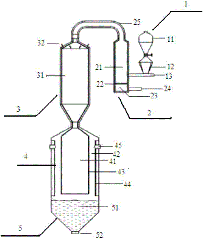
[0024] figure 1 For the module schematic diagram of the cascade combined bed gasification system of the present invention, please refer to figure 1 , the cascade combined bed gasification system of the present invention comprises a coal delivery unit 1, a primary fluidized bed gasification unit 2, a secondary entrained flow gasification unit 3, a waste heat recovery unit 4...


PUM

PropertyMeasurementUnit
particle diameteraaaaaaaaaa

Abstract

The invention provides a gradient combined bed gasification system which comprises a coal conveying unit, a first-stage fluidized bed gasification unit, a second-stage fluidized bed gasification unit, a waste heat recycling unit and a waste residue collecting unit, wherein the coal conveying unit is communicated with the first-stage fluidized bed gasification unit; the first-stage fluidized bed gasification unit is communicated with the second-stage fluidized bed gasification unit; the second-stage fluidized bed gasification unit is communicated with the waste heat recycling unit; the waste heat recycling unit is communicated with the waste residue collecting unit. By adopting the gradient combined bed gasification system provided by the invention, coal powder can be subjected to gradient gasification, so that high-efficiency conversion of coal can be achieved.

Description

technical field [0001] The invention relates to a coal gasification system, in particular to a cascaded combined bed gasification system, which belongs to the technical field of clean and efficient utilization of coal. Background technique [0002] Coal gasification technology is the process of converting solid coal that is difficult to process and remove useless components into gas that is easy to purify and apply. In short, it is to convert the carbon and hydrogen elements of coal into clean fuel gas or Syngas process. [0003] The existing coal gasification technology can be divided into fixed bed, fluidized bed and entrained bed according to the contact mode of coal and gasification agent. Due to the high requirements for coal types (lump coal with a particle size of 38mm), the fixed bed technology has been gradually eliminated because the gas contains pollutants such as tar and phenol cyanide; although the fluidized bed technology has low requirements for coal types (f...

Claims


Application Information

Patent Timeline
Patent Type & Authority Applications(China)
IPC IPC(8): C10J3/48C10J3/56C10J3/72
CPCC10J3/485C10J3/56C10J3/721C10J2300/0936Y02P20/129
Inventor 彭敏刘欣毕大鹏刘淑媛黄成龙
Owner KEDA MAS CLEAN ENERGY
Learn More