Natural gas dewatering device

A dehydration device, natural gas technology, applied in the direction of gas fuel, petroleum industry, fuel, etc., can solve the problem that zero emission cannot be achieved

Inactive Publication Date: 2016-11-16
BC P INC CHINA NAT PETROLEUM CORP +2
View PDF5 Cites 2 Cited by
  • Summary
  • Abstract
  • Description
  • Claims
  • Application Information

AI Technical Summary

Problems solved by technology

[0004] Before storage and transportation, natural gas needs to be cleaned of impurities and dehydrated; in the prior art, other media are needed for cleaning of impurities and dehydration, and zero discharge cannot be achieved

Method used


Image

  • Natural gas dewatering device
  • Natural gas dewatering device
  • Natural gas dewatering device

Examples


Embodiment Construction

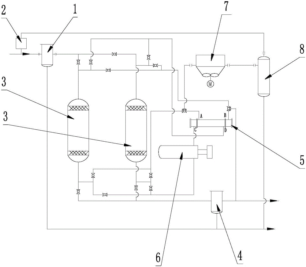
[0030] The principles and features of the present invention are described below in conjunction with the accompanying drawings, and the examples given are only used to explain the present invention, and are not intended to limit the scope of the present invention.

[0031] like figure 1 As shown, a natural gas dehydration device includes a first filter separator 1, two parallel molecular sieve dehydration towers 3, a second filter separator 4, a U-shaped tube heat exchanger 5, an electric heating device, a cooler 7 and a gas-liquid Separator 8; molecular sieve dehydration tower 3 is vertically arranged, molecular sieve dehydration tower 3 has dehydration tower air inlet and dehydration tower air outlet, dehydration tower air inlet is arranged on the top of molecular sieve dehydration tower 3, dehydration tower air outlet is arranged on molecular sieve dehydration Tower 3 bottom. In order to clearly describe the connection relationship, the four ports of the U-shaped tube heat ...


PUM


Abstract

The invention relates to a natural gas dewatering device. A net gas outlet of a first filter separator is connected with an inlet of a molecular sieve dewatering tower, and an outlet of the molecular sieve dewatering tower is connected with an external conveying dry gas pipeline; one end of a heating inlet pipe is connected with the external conveying dry gas pipeline, and the other end of the heating inlet pipe is connected with an opening of the molecular sieve dewatering tower; one end of a cold blowing pipe is connected with the external conveying gas pipeline, and the other end of the cold blowing pipe is connected with an opening of the molecular sieve dewatering tower. When the natural gas is dewatered, the natural gas to be treated only needs to be sequentially introduced into the first filter separator and the molecular sieve dewatering tower; the dewatered and heated natural gas is introduced into the molecular sieve dewatering tower to dry molecular sieve balls, and then the dewatered natural gas is introduced into the molecular sieve dewatering tower to cool the molecular sieve balls, so that the water absorption of the molecular sieve balls is restored.

Description

technical field [0001] The invention relates to a natural gas treatment device, in particular to a natural gas dehydration device. Background technique [0002] During the development of large-scale oil and gas fields, some remote and scattered gas wells have not been utilized due to reasons such as unrealized reserves, small production, or remote location of the gas wells. Some wells are shut down, and some are vented and burned. Today, with the increasing calls for environmental protection, such waste is astonishing, and the pollution to the environment is also extremely serious. [0003] For low-yield oil and gas well natural gas in remote and scattered areas where it is difficult to lay pipelines or be utilized locally, it is recommended to develop by adopting a small mobile compressed natural gas (CNG) cylinder storage and transportation solution. [0004] Before storage and transportation, natural gas needs to be treated with impurity removal and dehydration; in the p...

Claims


Application Information

Patent Timeline
Patent Type & Authority Applications(China)
IPC IPC(8): C10L3/10
CPCC10L3/106
Inventor 胡成勇张硕王元春周岩张利江陈鹏轩张井鲁
Owner BC P INC CHINA NAT PETROLEUM CORP
Why Eureka
Try Eureka