Sand core drying equipment

A technology for drying equipment and sand cores, which is applied in drying, drying machines, lighting and heating equipment, etc. It can solve the problems of affecting the quality of casting products, easy deformation of sand cores, and long drying time, etc., and achieves the goal of providing drying Efficiency, protection against radiation damage, and easy operation

Active Publication Date: 2016-11-16
NINGXIA KOCEL MACHINE TOOL ACCESSORIES
View PDF7 Cites 13 Cited by
  • Summary
  • Abstract
  • Description
  • Claims
  • Application Information

AI Technical Summary

Problems solved by technology

At present, according to our market research, in the machinery industry, electric furnace drying, fuel drying and other drying processes are generally used for casting sand cores. The control is a simple electronic control system, which is controlled by many intermediate relays, which is large in size and poor in reliability. High failure rate
During the drying process, the user cannot set the operating parameters according to the characteristics of the sand core, which not only wastes energy, but also takes a long time to dry and the sand core is easily deformed
In addition, the whole drying system also has the disadvantages of high noise and environmental pollution.
The above disadvantages not only increase the cost, but also affect the quality of casting products
For example, the patent document with the announcement number CN 201184739U discloses a coal-fired oven for casting oil sand cores, which is coal-fired and dried, and has high noise, and the exhausted flue gas also pollutes the environment, has poor reliability and high failure rate

Method used


Image

  • Sand core drying equipment
  • Sand core drying equipment
  • Sand core drying equipment

Examples


Embodiment Construction

[0024] In order to enable those skilled in the art to better understand the technical solutions of the present invention, the present invention will be further described in detail below in conjunction with specific examples. The orientation words such as "up, down, left, right, front, back and side" used in the description do not limit the present invention in any way.

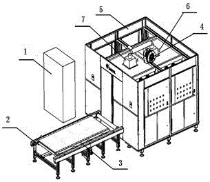
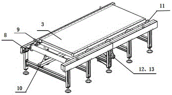
[0025] Such as figure 1 As shown, a drying equipment of the present invention includes: a control electric cabinet 1, a roller conveying device and a drying furnace main body 5; wherein, the control electric cabinet 1 is arranged on the left side of the drying furnace main body 5, and the control There is a power button inside the electric cabinet 1, which controls the start of the drying equipment, drives the rotating drum 10 to operate, transports the tray 3 to the main body of the drying furnace 5, dries the sand cores placed on the tray 3, and controls the electric cabinet 1 A program controller is instal...


PUM


Abstract

The invention relates to the field of drying devices, in particular to sand core drying equipment. The sand core drying equipment comprises a roller way conveying device, a control electric cabinet and a drying furnace main body, wherein the roller way conveying device includes an external high-load roller way, a tray, a travel switch a, a travel switch b, a power roller, an aluminum stop edge, a chain wheel and a speed reducing motor; and the drying furnace main body includes such components as a moisture discharge fan, a temperature sensor, a ventilation pipe, a rectangular wave guider, a magnetic control pipe module and a sealing door. The sand core drying equipment applies a microwave heating technology, can shorten the heating time and improve the efficiency, realizes continuous and quick drying of sand cores and paint and mechanization and automation of core making parts, adopts a metal plate labyrinth structure, adds silicon rubber bars capable of absorbing microwaves in structural gaps, reduces the microwave leakage to the greatest extent, and prevents the radiation injury of the microwave leakage to human bodies.

Description

technical field [0001] The invention relates to the field of drying devices, in particular to a drying device for mold sand cores with high speed and low energy consumption. Background technique [0002] Casting in the mechanical processing industry is labor-intensive and the working environment is poor. With the increasingly fierce competition in the market economy, its profit margins are also shrinking. As we all know, sand core molding is an important process, which directly affects the quality of casting products. At present, according to our market research, in the machinery industry, electric furnace drying, fuel drying and other drying processes are generally used for casting sand cores. The control is a simple electronic control system, which is controlled by many intermediate relays, which is large in size and poor in reliability. High failure rate. During the drying process, the user cannot set the operating parameters according to the characteristics of the sand ...

Claims


Application Information

Patent Timeline
Patent Type & Authority Applications(China)
IPC IPC(8): F26B9/10F26B21/00F26B23/08F26B25/00F26B25/12
CPCF26B3/347F26B9/10F26B21/006F26B25/003F26B25/12
Inventor 齐亚文兰浩南丁菲菲闫德刚俞科车志宏
Owner NINGXIA KOCEL MACHINE TOOL ACCESSORIES
Why Eureka
Try Eureka