Eureka AIR delivers breakthrough ideas for toughest innovation challenges, trusted by R&D personnel around the world.

Rectangular slow wave line used for traveling wave tube

A technology of traveling wave tube and slow wave line, applied in the field of microwave vacuum electronic devices, can solve the problems of small size, narrow bandwidth and small power capacity of slow wave structure devices

Inactive Publication Date: 2016-11-16
UNIV OF ELECTRONICS SCI & TECH OF CHINA
View PDF4 Cites 13 Cited by
  • Summary
  • Abstract
  • Description
  • Claims
  • Application Information

AI Technical Summary

Problems solved by technology

Although the helical slow wave structure has the advantage of frequency bandwidth, its power capacity is relatively small due to the limitation of the heat dissipation capacity of the helix; although the coupled cavity slow wave structure has an order of magnitude higher power level than the helix, due to the band edge oscillation effect, its narrow bandwidth
[0004] In addition, with the development of traveling wave tubes to millimeter waves and higher frequency bands, the size of slow wave structure devices will become very small, and traditional helical wires and coupled cavities will face great difficulties and challenges in precision machining and assembly

Method used

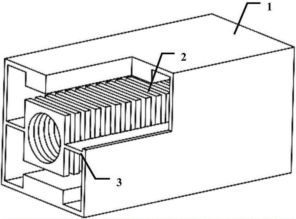
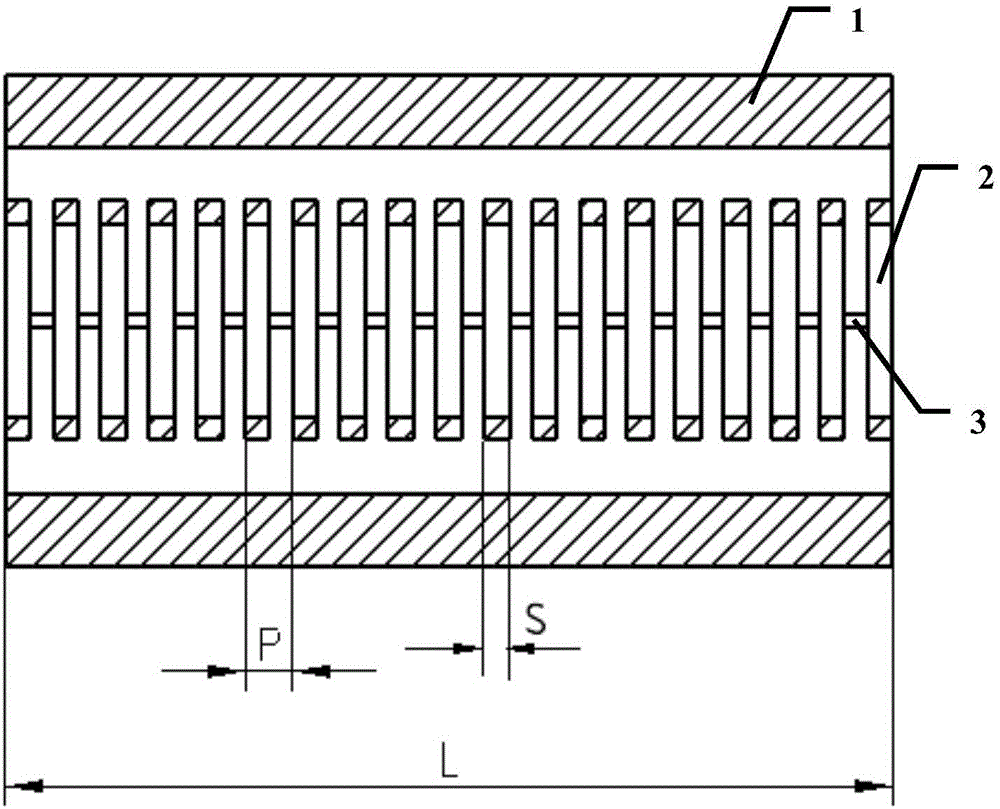
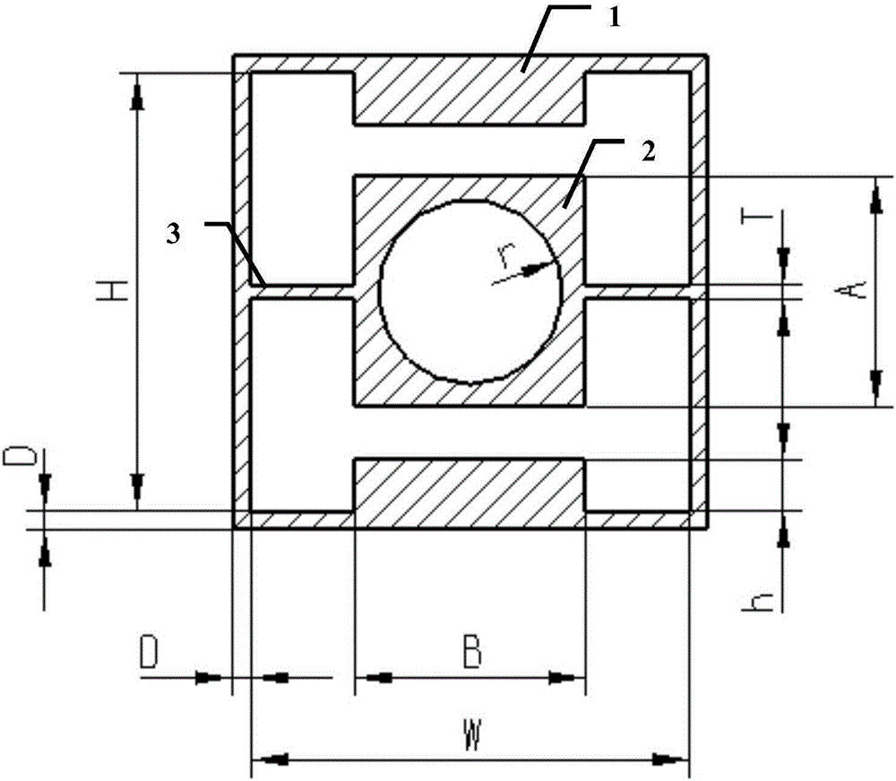

Image

  • Rectangular slow wave line used for traveling wave tube
  • Rectangular slow wave line used for traveling wave tube
  • Rectangular slow wave line used for traveling wave tube

Examples


Embodiment Construction

[0021] Specific embodiments of the present invention will be described below in conjunction with the accompanying drawings, so that those skilled in the art can better understand the present invention. It should be noted that in the following description, when detailed descriptions of known functions and designs may dilute the main content of the present invention, these descriptions will be omitted here.

[0022] Rectangular slow wave line (slow wave structure) as authorized on December 2, 2015, the announcement number is CN103632905B trapezoidal line structure slow wave line, because it is a kind of all metal structure slow wave line, it has good heat dissipation performance and large power capacity , in addition to its good overall structural consistency, the processing and assembly accuracy is easier to be guaranteed, so it has been widely used in millimeter wave traveling wave tubes.

[0023] The present invention is based on the above-mentioned advantages of the rectangu...


PUM


Abstract

The invention discloses a rectangular slow wave line used for a traveling wave tube. A rectangular ridge waveguide is used as a rectangular shielding cylinder; on the basis of the rectangular shielding cylinder, n, or n+1, or n-1 metal rectangular rings with square externals and circular internals and two metal flat plates are provided additionally; the centers of the metal rectangular rings are overlapped with the central axis of the rectangular ridge waveguide, and are periodically distributed in an axial direction; the internal circular parts of the metal rectangular rings form an electron beam channel of the traveling wave tube; and the metal rectangular rings and the outer shielding cylinder are connected together by the two metal flat plates which are arranged parallel to the wide edge of the rectangular shielding cylinder between the metal rectangular rings and narrow edge of the rectangular shielding cylinder. Therefore, the all-metal slow wave line is formed; the slow wave line is directly connected with the rectangular shielding cylinder, so that the thermal conductivity is greatly improved; the coupling impendence is higher; the power capacity is increased; a ridge loaded structure is adopted, so that a relatively wide bandwidth is realized; meanwhile, the rectangular slow wave line is simple to process, high in integrality, high in processing precision, simple to assemble and good in the radiating effect; and furthermore, the precision of the slow wave tube can be ensured easily.

Description

technical field [0001] The invention belongs to the technical field of microwave vacuum electronic devices, and more specifically relates to a beam-wave interaction structure of a traveling wave tube: a rectangular slow wave line. Background technique [0002] Traveling wave tube is the most widely used microwave power amplifier device in the field of vacuum microwave electronics. It has the characteristics of high power, high efficiency, high gain, wide frequency bandwidth and long life. It is widely used in radar, guidance, interference, communication, In fields such as microwave remote sensing and radiation measurement, its performance directly determines the level of equipment. The slow wave line (slow wave structure) is the core component of the beam-wave interaction, and its performance directly determines the technical level of the traveling wave tube. [0003] Helix and its metamorphosis and coupled cavity have been the two most widely used slow wave structures in t...

Claims


Application Information

Patent Timeline
IPC IPC(8): H01J23/24
CPCH01J23/24
Inventor 岳玲娜黄建斌王文祥赵国庆唐涛徐进魏彦玉宫玉彬
Owner UNIV OF ELECTRONICS SCI & TECH OF CHINA
Why Eureka
Eureka Blog
Learn More