Waste gas treatment process and device adopting reverse flow counter-impact turbulence washing tower

A waste gas treatment device and waste gas treatment technology, applied in the direction of gas treatment, use of liquid separation agent, membrane technology, etc., can solve the problems of easy blockage of fillers and nozzles, complicated process flow, low desulfurization efficiency, etc., and achieve simple structure and high efficiency desulfurization Exhaust gas removal and removal efficiency are high

Inactive Publication Date: 2016-11-23
浙江海牛环境科技股份有限公司
View PDF8 Cites 10 Cited by
  • Summary
  • Abstract
  • Description
  • Claims
  • Application Information

AI Technical Summary

Problems solved by technology

[0011] Obviously, the above-mentioned desulfurization technologies disclosed above either have low desulfurization efficiency,

Method used


Image

  • Waste gas treatment process and device adopting reverse flow counter-impact turbulence washing tower

Examples


Example Embodiment

[0038] Example 1

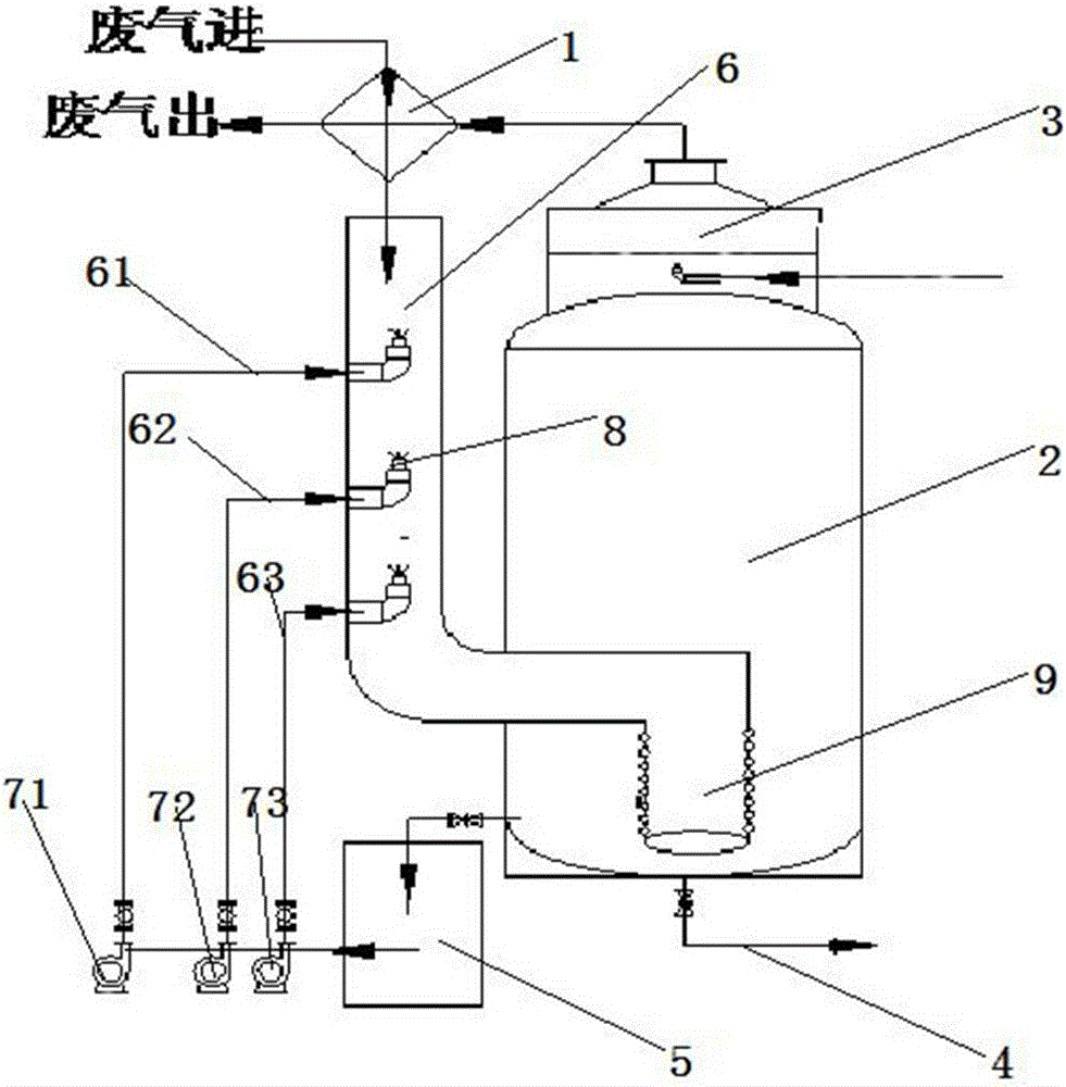
[0039] like figure 1 The device for treating exhaust gas using a countercurrent flushing turbulent scrubber includes a heat exchanger 1, a countercurrent scrubber 2, a demister 3, a saturated liquid discharge pipe 4, an absorption liquid circulation tank 5, and a circulation pump. The countercurrent scrubber is provided with a reverse spray scrubber 6, one end of the reverse spray scrubber is connected to the heat exchanger, and the other end goes deep into the bottom of the countercurrent scrubber, the reverse spray scrubber is provided with a reverse spray structure, and the reverse spray structure passes through The circulating pump is connected to the pipeline of the absorption liquid circulation tank, the demister is arranged on the top of the countercurrent scrubber, the demister is connected to the heat exchanger through a pipeline, and the saturated liquid outlet pipe is arranged at the bottom of the countercurrent scrubber, The countercurrent washi...

Example Embodiment

[0041] Example 2

[0042] A kind of waste gas treatment process using a countercurrent countercurrent turbulent scrubber waste gas treatment device as described in Example 1 includes the following steps:

[0043] (1) The exhaust gas passes through the heat exchanger and enters the reverse spray washing pipe of the countercurrent scrubber, and contacts with the upward spraying primary reverse spray, secondary reverse spray or tertiary reverse spray absorption liquid circulation system to obtain a mixed absorption liquid, forming Gas-liquid turbulent foam washing zone;

[0044] (2) The mixed absorption liquid enters the bottom of the countercurrent washing tower along the flow, and enters the perforated pipe to form a gas-liquid or liquid-liquid bubbling washing area.

[0045] (3) The exhaust gas after passing through the bubbling washing area passes through the demister, and then through the outlet of the heat exchanger to discharge the purified exhaust gas.

[0046] When exh...


PUM


Abstract

The invention provides a waste gas treatment process and device adopting a reverse flow counter-impact turbulence washing tower. The process includes following steps: enabling waste gas to pass a heat exchanger and enter a reverse spray washing pipe of the reverse flow washing tower to contact with a first-stage reverse spray, second-stage reverse spray or third-stage reverse spray absorbing liquid circulating system which sprays flow upwards to obtain mixed absorbing liquid, and forming a gas-liquid turbulence foam washing area; enabling the mixed absorbing liquid to enter the bottom of the reverse flow washing tower along the flow and enter a holed pipe to form a gas-liquid or liquid-liquid bubble washing area, enabling the waste gas after going through the bubble washing area to pass a defoamer and then an outlet of the heat exchanger, and discharging the waste gas after being purified. The waste gas treatment process and device has the advantages that gas-liquid counter-impact is utilized to increase contact specific surface area of the waste gas and the absorbing liquid to form the turbulence foam washing area, and the three reverse spray absorbing liquid circulating systems are designed creatively; natural gravity of the reverse spray absorbing liquid is utilized, and pipe wall hole diameter of 1-20mm is designed at the bottom of the reverse spray washing pipe creatively to form the bubble washing area.

Description

technical field [0001] The invention relates to the field of environmental protection treatment of waste gas, including the upgrading and transformation of waste gas in petrochemical, electric power and other industries, especially related to sulfur plant SO 2 Disclosed is a waste gas treatment process and device of a counter-flow hedging type turbulent scrubber for tail gas discharge treatment. Background technique [0002] SO in the atmosphere 2 Sulfuric acid mist and sulfuric acid rain can be formed. When the humidity is high, the temperature is low and there are particles, sulfuric acid mist is easy to form, which will increase the haze and cause harm to human health. In this regard, the state has issued many policies and regulations to control SO 2 emissions. For example, in the national standard GB16297~1996, the smoke emission standard SO 2 ≤960mg / m 3 , now facing the increasingly severe environmental situation, GB31570-2015 "Petroleum Refining Industry Pollutant...

Claims


Application Information

Patent Timeline
IPC IPC(8): B01D53/78B01D53/50B01D47/06
CPCB01D53/78B01D47/06B01D53/501B01D2251/404B01D2251/604B01D2257/302
Inventor 李超陆侨治谢伟淼张斌
Owner 浙江海牛环境科技股份有限公司
Why Eureka
Try Eureka