
Multifunctional polishing machine

A polishing machine, multi-functional technology, applied in the direction of grinding/polishing equipment, grinding/polishing safety devices, grinding machines, etc., can solve the problem of easy grinding between the grinding tool and the metal workpiece, and the processing function of a single grinding tool is less , affect the processing quality and other issues, achieve the effect of convenient tool change, reduce calculation and setting time, and avoid human injury

Inactive Publication Date: 2016-11-23
苏州欧复能新材料科技有限公司
View PDF0 Cites 3 Cited by
  • Summary
  • Abstract
  • Description
  • Claims
  • Application Information

AI Technical Summary

Problems solved by technology

In the existing automatic polishing equipment, a variety of grinding tools are used to realize the functions of milling plane, milling chamfer, milling notch, grinding plane and grinding chamfer, but a large amount of waste will be generated during the polishing process, and some of the waste Splashing outward under the rotation of the grinding tool may easily cause human injury and pollute the environment, and another part of the waste stays on the metal workpiece, but the waste staying on the metal workpiece is easy to grind into the gap between the grinding tool and the metal workpiece. Causes scratches on metal workpieces, resulting in reduced polishing effect and affecting processing quality
Moreover, many of the existing grinding tools are customized for a single step or a single process of the product, which has poor versatility, a single grinding tool has few processing functions, and the planning is not clear

Method used


Image

  • Multifunctional polishing machine
  • Multifunctional polishing machine
  • Multifunctional polishing machine

Examples


Embodiment Construction

[0018] The technical solution of this patent will be described in further detail below in conjunction with specific embodiments.

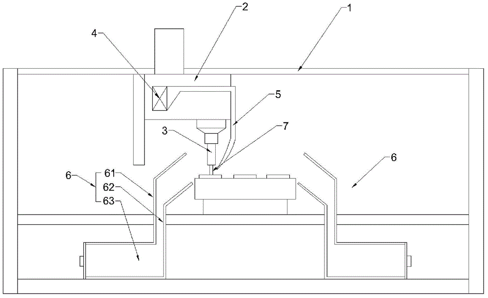
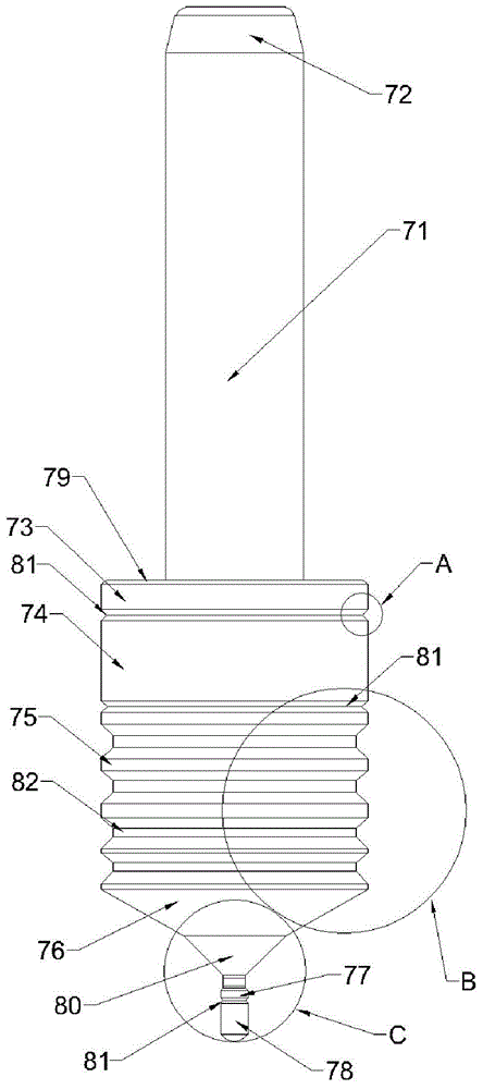
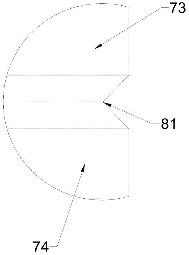
[0019] See Figure 1-5 , A multifunctional polishing machine, including a main frame 1, the main frame 1 is provided with a spindle drive part 2 that can move in the vertical and horizontal directions, and further, the spindle drive part 2 can be controlled by a numerical control device and automatically Vertical movement and horizontal movement to automatically grind the workpiece, the spindle drive part 2 drives a transmission spindle 3 to rotate, the transmission spindle 3 is located above the workpiece, and the end of the transmission spindle 3 is equipped with a grinding tool 7. The grinding tool 7 includes a tool holder 71, which facilitates the clamping of the tool on the spindle of the machining center. The upper end of the tool holder 71 has a tool guide portion 72, which is tapered, and its upper end has a circular arc chamfer, which can be ...


PUM


Abstract

The invention discloses a multifunctional polishing machine, which comprises a main rack. A main shaft drive part moving in a vertical direction and a horizontal direction is arranged on the main rack, and drives a transmission main shaft to rotate; the transmission main shaft is located above a metal piece; a grinding cutter is arranged on the end part of the transmission main shaft, and comprises a cutter handle; a cutter guiding part is arranged on the upper end part of the cutter handle; a cutter body is arranged on the lower end part of the cutter handle; a fan and a gooseneck pipe are fixed to the main shaft drive part; one end of the gooseneck pipe communicates with an air outlet of the fan; the other end of the gooseneck pipe extends to the grinding cutter and towards the grinding end of the grinding cutter; and waster recovery mechanisms are arranged on two sides of a conveyor belt. According to the multifunctional polishing machine provided by the invention, wastes can be better recovered so as to be prevented from causing human body injury and environment pollution, the structure layer of the cutter is clearer, and the computing and setting time during programming is reduced.

Description

Technical field [0001] The invention relates to the field of electromechanical equipment, in particular to a multifunctional polishing machine. Background technique [0002] Metal surface polishing technology is an important part of the field of surface technology and engineering disciplines, and is widely used in industrial production processes, especially in the electroplating industry, coating, anodizing and various surface treatment processes. With the rapid development of the national economy, it has expanded to areas other than surface treatment technology and has gradually become a relatively independent special technology. In the existing automatic polishing equipment, a variety of grinding tools are used to realize the functions of milling, milling and chamfering, milling notches, grinding and chamfering, but a large amount of waste will be generated during the polishing process, of which some waste Under the action of the rotation of the grinding tool, it splashes outw...

Claims


Application Information

Patent Timeline
IPC IPC(8): B24B25/00B24B55/02B24B55/12
CPCB24B25/00B24B55/02B24B55/12
Inventor 陈树丽
Owner 苏州欧复能新材料科技有限公司
Learn More