
Detachable hydraulic cylinder with carbon fiber composite for connection and load bearing

A composite material and carbon fiber technology, applied in cylinders, fluid pressure actuators, engine components, etc., can solve the problems of high maintenance cost of composite hydraulic cylinders, high quality of all-metal hydraulic cylinders, and weakened load-bearing structures, etc., to improve equipment Economical, maintaining structural integrity, and improving dynamic characteristics

Active Publication Date: 2016-11-23
ZHEJIANG UNIV
View PDF5 Cites 8 Cited by
  • Summary
  • Abstract
  • Description
  • Claims
  • Application Information

AI Technical Summary

Problems solved by technology

[0005] The purpose of the present invention is to address the deficiencies of the prior art, to provide a design scheme of a detachable hydraulic cylinder that adopts carbon fiber composite material connection and bearing, and to solve the problems of high mass and unsatisfactory power-to-weight ratio of all-metal hydraulic cylinders in the prior art; At the same time, it provides an inlaid connection method that can realize reliable connection without destroying the structural integrity of carbon fiber composite materials, and solves the problem that the connection of existing composite hydraulic cylinders weakens the load-bearing structure; at the same time, a hydraulic cylinder with an independent cylinder structure is proposed. Cylinder design to solve the problem of high maintenance cost of existing composite material hydraulic cylinders

Method used


Image

  • Detachable hydraulic cylinder with carbon fiber composite for connection and load bearing
  • Detachable hydraulic cylinder with carbon fiber composite for connection and load bearing

Examples


Embodiment Construction

[0023] The present invention will be further described below in conjunction with the accompanying drawings.

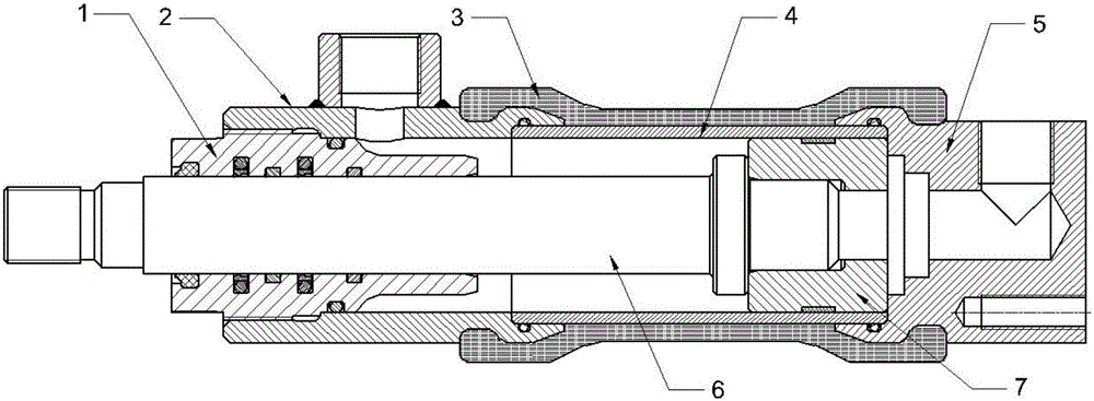
[0024] Such as figure 1 As shown, the detachable hydraulic cylinder provided by the present invention is connected and carried by carbon fiber composite material is basically the same structure as the traditional hydraulic cylinder, except that the outer layer of the cylinder is made of 3-series composite material, and the sealing ring, dustproof ring, support ring, Guide rings are selected in accordance with the national standard, except for the corresponding standard parts, and other parts are made of No. 45 steel. The hydraulic cylinder of the present invention comprises an end cover 1, a cylinder head 2, a cylinder outer layer 3, a cylinder liner 4, a cylinder bottom 5, a piston rod 6 and a piston 7; the cylinder head 2, the cylinder bottom 5, the cylinder liner 4 The three constitute the metal part of the cylinder assembly; the outer layer 3 of the cylinder uses ...


PUM

PropertyMeasurementUnit
Winding angleaaaaaaaaaa

Abstract

The invention discloses a detachable hydraulic cylinder with a carbon fiber composite for connection and load bearing. The detachable hydraulic cylinder comprises an end cap, a cylinder head, a cylinder barrel outer layer, a cylinder barrel lining, a cylinder bottom, a piston rod and a piston. The cylinder barrel outer layer is formed by adopting high-strength carbon fibers as reinforcing material and epoxy resin as a substrate, and winding the carbon fibers on a cylinder barrel assembly metal part by adoption of a contact molding method. Compared with a metal hydraulic cylinder, the detachable hydraulic cylinder has the advantage of being remarkably low in weight; compared with an existing composite hydraulic cylinder, by adopting a composite body as the connection structure, the reliability is higher than that of adhesive connection; due to the fact that threads, bolts and pins are not adopted for connection between the composite and metal parts, the composite structure is not locally damaged by machining, the continuity and integrity of the carbon fibers are guaranteed, and the advantage of high strength of the carbon fibers is given full play to the greatest extent; and a cylinder barrel assembly can be separated from other assemblies, so that the maintenance cost and difficulty of the detachable hydraulic cylinder are lower than those of an integral composite hydraulic cylinder.

Description

technical field [0001] The invention relates to a detachable hydraulic cylinder connected and carried by carbon fiber composite material. Background technique [0002] The development trend of hydraulic actuators is lightweight and high power-to-weight ratio. Traditional metal hydraulic cylinders generally use high-strength steel as the structural material; a certain proportion of low-density materials, such as high-strength aluminum alloys, are used for occasions that require high weight control; The material acts as a load-bearing structure. [0003] The specific gravity of carbon fiber composite materials is much lower than that of steel; the tensile strength of carbon fiber is generally higher than 3500MPa, and the tensile strength of some carbon fiber materials can reach more than 4500MPa. These characteristics make carbon fiber reinforced composite materials have great advantages in manufacturing hydraulic cylinders. [0004] At present, some hydraulic cylinders mad...

Claims


Application Information

Patent Timeline
IPC IPC(8): F15B15/14F16J10/02F16J10/04F16J1/12B29C53/56
CPCB29C53/56F15B15/14F15B15/1428F15B15/1433F15B15/1438F15B15/1447
Inventor 徐兵鲍静涵张军辉王迪
Owner ZHEJIANG UNIV
Learn More