Method for rapidly determining passive intermodulation level of cavity filter
A cavity filter and passive intermodulation technology, which is applied to waveguide devices, instruments, circuits, etc., can solve the problems that restrict the development of low passive intermodulation and high-power microwave components, and the passive intermodulation performance of products cannot be guaranteed. , to achieve good results
- Summary
- Abstract
- Description
- Claims
- Application Information
AI Technical Summary
Problems solved by technology
Method used
Image


Examples
Embodiment
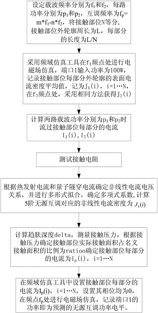
[0041] Here, a second-order aluminum alloy cavity filter is taken as an example to introduce the implementation process of the method of the present invention. The process is as follows figure 1 shown.
[0042] (1) Carrier power f 1 =2.16GHz, f 2 =2.21GHz, m=3, n=2, 5th-order passive intermodulation frequency f p =2.06GHz,P 1 =P 2 =100W, divide the contact part into 8 equal parts, the perimeter of the contact part is L=42.4e-3m, and the length of each part is 5.3e-3m;
[0043] (2) The frequency domain simulation tool Ansys HFSS is used to perform electromagnetic field simulation at 2.16GHz, the input power of the input port is 100W, and the average surface current density of each part of the outer contour of the contact part is:
[0044] J 1 =[28.53,24.48,22.02,24.97,27.31,28.97,30.83,32.49]A / m
[0045] The frequency domain simulation tool Ansys HFSS is used to simulate the electromagnetic field at 2.21GHz, the input power of the input port is 100W, and the average surf...
PUM
 Abstract
Description
Claims
Application Information
 - Generate Ideas
- Intellectual Property
- Life Sciences
- Materials
- Tech Scout
- Unparalleled Data Quality
- Higher Quality Content
- 60% Fewer Hallucinations
Browse by: Latest US Patents, China's latest patents, Technical Efficacy Thesaurus, Application Domain, Technology Topic, Popular Technical Reports.
© 2025 PatSnap. All rights reserved.Legal|Privacy policy|Modern Slavery Act Transparency Statement|Sitemap|About US| Contact US: help@patsnap.com