Sealing structure used for moderate and high temperature battery, moderate and high temperature battery, and assembling method of sealing structure

A sealed structure, medium and high temperature technology, used in sealing materials, secondary batteries, structural parts, etc., can solve the problems of unsecured sealing, complicated processes, and inability to achieve effective sealing, achieve a wide range of use temperatures, avoid The effect of seal failure and excellent liquid sealing performance

Inactive Publication Date: 2016-11-23
润高投资有限公司
View PDF11 Cites 3 Cited by
  • Summary
  • Abstract
  • Description
  • Claims
  • Application Information

AI Technical Summary

Problems solved by technology

[0004] In the sealing design of high-temperature liquid metal batteries, most of them adopt the principle of assembly to achieve sealing, such as "a liquid metal battery device" (application number 201420780918.8), "semi-liquid metal electrode energy storage battery" (application number 201310131587.5) and other patents The insulating ceramic ring insulation used in the battery is installed or fastened, and the sealing performance cannot be guaranteed, and the battery structure of the above-mentioned patent is complex and bulky
[0005] For another example, patents such as "A Liquid Metal Battery Device and Its Assembly Method" (Application No. 201410350077.1) mention that "using sealed insulating ceramic parts to fasten the top of the metal current lead-out rod to the battery case" achieves sealing and insulation. The ceramic is only fastened on the metal current lead-out rod, so this sealing method ca

Method used


Image

  • Sealing structure used for moderate and high temperature battery, moderate and high temperature battery, and assembling method of sealing structure
  • Sealing structure used for moderate and high temperature battery, moderate and high temperature battery, and assembling method of sealing structure

Examples


Embodiment Construction

[0030] The present invention will be described in further detail below in conjunction with the accompanying drawings and embodiments. The specific embodiments described herein are only for explaining the present invention.

[0031] In the present invention, the closed space enclosed by the battery casing and containing the electrolyte is the "inner" side / part of the battery, and the opposite open space separated by the battery casing is the "outer" side / part. "Up" and "down" are understood according to the upper and lower relationship depicted in the figure.

[0032] The sealing structure of the present invention is suitable for medium-high temperature energy storage batteries, for example, sodium-sulfur batteries, liquid metal batteries and the like.

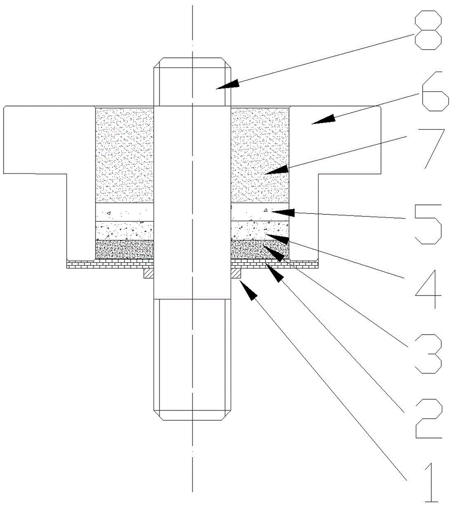
[0033] Such as figure 1 As shown, a sealing structure for a high-temperature battery in a specific embodiment of the present invention. When this structure is applied to a battery, the metal rod 8 can be connected to the pos...


PUM

PropertyMeasurementUnit
Melting pointaaaaaaaaaa

Abstract

The invention relates to a sealing structure used for a moderate and high temperature battery, the moderate and high temperature battery, and an assembling method of the sealing structure. The sealing structure comprises a metal part used for leading out curren; a sealing cavity used for sealing an assembling gap is arranged on the inner side of a battery on the assembling gap, where the metal part is assembled, on the battery; the metal part passes through the sealing cavity; one layer, two layers, three layers or more than three layers of salt layers used for liquid seal are arranged in the sealing cavity; each salt layer is arranged from one side of the inner side of the battery to one side of the outer part of the battery, and the melting points successively lower. The sealing structure disclosed by the invention has excellent gas tightness and anti-corrosion property, the service life of the moderate and high temperature battery when the moderate and high temperature battery works at the temperature of 150-700DEG C is guaranteed, meanwhile, the sealing structure also has an insulation characteristic, volume occupied by battery sealing is greatly reduced under a condition that mechanical strength is guaranteed, and space is saved.

Description

technical field [0001] The invention belongs to the technical field of energy storage batteries, and in particular relates to a sealing structure for a medium-high temperature battery and an assembly method thereof. Background technique [0002] Among the existing electrochemical energy storage technologies, medium and high temperature energy storage batteries such as sodium-sulfur batteries, liquid metal batteries and other energy storage technologies have the characteristics of no pollution, high energy efficiency, flexible power and energy matching output, long life, low The maintenance cost and other advantages make it an energy storage technology with very good application prospects. [0003] The electrode materials of medium and high temperature batteries mostly use one or more of alkaline metals such as lithium, sodium, and magnesium. When the battery is working in a medium and high temperature environment (between 150°C and 700°C), the electrode material or electroly...

Claims


Application Information

Patent Timeline
IPC IPC(8): H01M2/08H01M10/38H01M10/39
CPCH01M10/38H01M10/3909H01M10/399H01M50/183Y02E60/10Y02P70/50
Inventor 黎朝晖蒋凯王康丽张玘胡林徐振轩李建颖方瑛何亚玲
Owner 润高投资有限公司
Why Eureka
Try Eureka