LED driving control circuit, control device and control method

A LED drive and control circuit technology, applied in lighting devices, electric light sources, electrical components, etc., can solve the problems of incompatibility with high and low voltage input, large power loss, poor compatibility, etc., to achieve strong practicability, high compatibility, The effect of ingenious circuit design

Active Publication Date: 2016-11-23
SHENZHEN LEDFRIEND OPTOELECTRONICS
View PDF8 Cites 7 Cited by
  • Summary
  • Abstract
  • Description
  • Claims
  • Application Information

AI Technical Summary

Problems solved by technology

However, the core of these solutions is to meet the maintenance current by adding an additional dummy load, which brings about a lot of power loss and low efficiency; different thyristors need to adjust different dummy load cut-in points, and the compatibility is poor; It cannot be compatible with high and low voltage input at the same time, and it needs to be debugged separately, so the adaptability is poor
These do not meet the needs of the present and future energy-saving development and intelligent control

Method used


Image

  • LED driving control circuit, control device and control method
  • LED driving control circuit, control device and control method
  • LED driving control circuit, control device and control method

Examples


Embodiment Construction

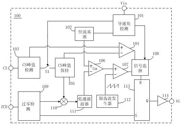
[0032] like figure 1 As shown, the LED drive control circuit 100 proposed by the present invention includes: a conduction angle detection circuit 101, a constant current reference circuit 102, a CS peak detection circuit 103, a CS peak hold circuit 105, a switch S1, a zero-crossing detection circuit 109, a first Comparator 107, second comparator 104, error amplifier 106, multiplier 110, low-pass filter 111, sawtooth wave generator 112, signal selection circuit 108, RS flip-flop 113 and switch drive circuit 114, the specific circuit connection relationship is : the input end of the conduction angle detection circuit 101 is connected to the main circuit, receives the input voltage rectified by the main circuit, and outputs three roads, one road is connected with the signal selection circuit 108, and the other road is connected with the constant current reference circuit 102, One path is connected to the switch S1, the input end of the CS peak detection circuit 103 is connected t...


PUM


Abstract

The invention discloses an LED driving control circuit, a control device and a control method. The LED driving control circuit comprises a conduction angle detection circuit, a constant current reference circuit, a CS peak detection circuit, a CS peak holding circuit, a zero cross detection circuit and a control circuit, wherein the conduction angle detection circuit is used for judging on-off state of a silicon controlled rectifier by detecting rectified input voltage and outputting an on-off state signal of the silicon controlled rectifier, and the control circuit realizes power factor correction, constant current output and switching of two control modes controlled by minimum holding current of the silicon controlled rectifier according to the on-off state signal of the silicon controlled rectifier. The LED driving control circuit has the advantages that a pure pseudo load is removed, energy consumption is reduced, intelligence and working efficiency are high, different silicon controlled rectifiers can be adaptive, compatibility is strong, input current is always higher than the minimum holding current of the silicon controlled rectifier, light flashing phenomenon can not be caused, different high and low voltage inputs can be adapted, circuit design is smart, and practicability is strong.

Description

technical field [0001] The present invention relates to the technical field of LED lighting drive power electronics, and in particular to an LED power supply control circuit, a control device using the drive control circuit, and a control method based on the control device. Background technique [0002] The current silicon controlled rectifier LED dimming circuit, because of the device of the silicon controlled rectifier itself, requires the existence of a sustaining current to be continuously turned on. Therefore, for dimming LED power supply requirements, when outputting low power or dimming to low power, especially when high voltage (200-240VAC) is input for low power output or dimming to small conduction angle, the input current should be less than possible The thyristor maintains the current, and the thyristor will enter the off state. At this time, the circuit will interrupt the power input due to the shutdown of the thyristor, and flashing and restarting will occur. ...

Claims


Application Information

Patent Timeline
IPC IPC(8): H05B33/08H05B44/00
CPCH05B45/00
Inventor 朱俊高王斌范勇李少科
Owner SHENZHEN LEDFRIEND OPTOELECTRONICS
Why Eureka
Try Eureka