LED optical stimulation and electrographic recording integrating flexible neural electrode device and manufacturing method thereof

A technology of recording electrodes and stimulating electrodes, which is applied in the field of micro-electrodes in the field of biomedical engineering technology, can solve the problems that the relative position of LED light source and recording electrodes cannot be guaranteed, and has not been reported.

Active Publication Date: 2016-12-07
SHANGHAI JIAO TONG UNIV
View PDF14 Cites 21 Cited by
  • Summary
  • Abstract
  • Description
  • Claims
  • Application Information

AI Technical Summary

Problems solved by technology

The disadvantage of this method is that the LED light source is separated from the recording electrode, and the shaking of the light source or electrode will not be able to ensure the relative position of the LED light source and the recording electrode. If the light source touches the metal electrode point, the photoelectric effect will introduce spurious trace
[0008] In summary, there are certain problems in the above methods of combining LED light sources and ECoG recording electrodes reported so far, but there is no report in the literature that the combination of LED light stimulation electrodes and ECoG recording electrodes is prepared by gold wire ball bonding. Photoelectric integrated electrode device

Method used


Image

  • LED optical stimulation and electrographic recording integrating flexible neural electrode device and manufacturing method thereof
  • LED optical stimulation and electrographic recording integrating flexible neural electrode device and manufacturing method thereof
  • LED optical stimulation and electrographic recording integrating flexible neural electrode device and manufacturing method thereof

Examples


Embodiment 1

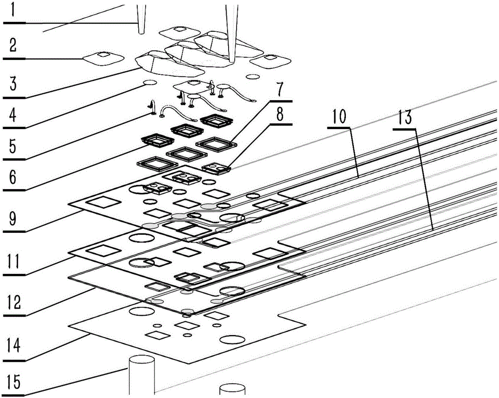
[0109] Such as figure 1 As shown, this embodiment provides a flexible nerve electrode device integrated with LED light stimulation and electrical recording, which is composed of light stimulation electrodes and recording electrodes;

[0110] The photo-stimulation electrode includes: a polyimide insulating layer 9 on the top layer of the photo-stimulation electrode, a metal layer 10 in the middle of the photo-stimulation electrode, and a polyimide insulating layer 11 at the bottom of the photo-stimulation electrode, wherein: the polyimide insulating layer on the top layer of the photo-stimulation electrode The amine insulating layer 9 and the bottom polyimide insulating layer 11 of the photo-stimulation electrode are provided with overlapping rectangular holes, circular holes and square holes, which are respectively used to ensure the light transmission of the micro-LED bare chip 8 and pass through the steel needle 1 and the Apply epoxy resin glue 2 to fix the relative position...

Embodiment 2

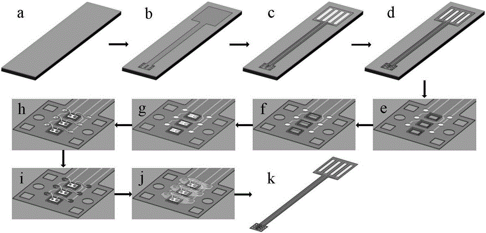
[0116] Such as Figure 2-Figure 4 As shown, this embodiment provides a method for preparing a flexible neural electrode device integrated with LED light stimulation and electrical recording, including:

[0117] 1. The preparation of photostimulation electrodes is carried out according to the following steps:

[0118] 1) if figure 2 As shown in middle a, a layer of 500 micron thick aluminum is deposited as a sacrificial layer on a 500 micron thick silicon wafer by sputtering or thermal evaporation;

[0119] 2) if figure 2 As shown in middle b, a layer of photosensitive polyimide Durimide 7510 is spin-coated, and after pre-baking, exposure, development and curing, a patterned polyimide insulating layer at the bottom of the photo-stimulation electrode is produced, and its thickness is 10 microns; There are three rectangular holes on the polyimide insulating layer at the bottom of the photo-stimulation electrode. There are two circular holes with a diameter of 300 microns an...

Embodiment 3

[0147] This embodiment provides a method for preparing a flexible nerve electrode device integrated with LED light stimulation and electrical recording similar to that of Embodiment 1, including:

[0148] 1. The preparation of photostimulation electrodes is carried out according to the following steps:

[0149] 1) Thermally evaporate a layer of 1.0 mm thick aluminum on a 500 micron thick silicon wafer as a sacrificial layer;

[0150] 2) Spin-coat a layer of photosensitive polyimide Durimide 7505, and through pre-baking, exposure, development and curing, make a patterned photo-stimulation electrode bottom polymer insulating layer 11 with a thickness of 5 microns; There are 3 rectangular holes on the bottom polymer insulating layer 11, the size of the rectangular holes is 190 microns × 270 microns, and the center distance is 700 microns; there are 2 circular holes on the bottom polymer insulating layer 11 of the photo-stimulation electrode, The circular hole has a diameter of 2...


PUM

PropertyMeasurementUnit
thicknessaaaaaaaaaa
thicknessaaaaaaaaaa
thicknessaaaaaaaaaa

Abstract

The invention provides an LED optical stimulation and electrographic recording integrating flexible neural electrode device and a manufacturing method thereof. The device comprises an optical stimulation electrode and a recording electrode, wherein both the optical stimulation electrode and the recording electrode comprise bottom polymer insulating layers, top polymer insulating layers and middle gold circuit layers; a plurality of holes are formed in the bottom polymer insulating layers and the top polymer insulating layers; steel pins sequentially run through the holes in the optical stimulation electrode and the recording electrode; and when the optical stimulation electrode and the recording electrode are in gluing connection, the optical stimulation electrode and the recording electrode are prevented from becoming displaced. According to the method, the optical stimulation electrode and the recording electrode are independently manufactured, and then the optical stimulation electrode and the recording electrode are bonded. According to the flexible neural electrode device disclosed by the invention, on the basis of direct contact between LED and brain tissues, light transparency is guaranteed, and meanwhile, influence on recording results due to a photoelectric effect between light and the recording electrode is effectively avoided; the electrodes, which are relatively thin, can guarantee shape preservation when attached to cerebral cortex; and the requirements of acute experiments and long-term implant experiments can be satisfied.

Description

technical field [0001] The invention relates to a microelectrode in the technical field of biomedical engineering, in particular to a flexible neural electrode device integrated with LED light stimulation and electrical recording and a preparation method thereof. Background technique [0002] Over the past few decades, electrical stimulation has brought enormous benefits to the study of brain function. To advance neuroscience further by studying how many neurons interact with each other in complex neural networks, it becomes necessary to selectively activate or inhibit a certain type of neuron, a function that electrical stimulation cannot effectively achieve. In recent years, optogenetics (Optogenetics) has brought revolutionary changes to the analysis of neural circuits. By introducing light-sensitive proteins (opsins) into specific types of cells, these cells can respond to light stimuli and have a clear pattern of action potentials. . [0003] By illuminating specific ...

Claims


Application Information

Patent Timeline
Patent Type & Authority Applications(China)
IPC IPC(8): A61N5/06
CPCA61N5/0622A61N2005/0643A61N2005/0651
Inventor 刘景全吉博文康晓洋王明浩杨斌陈翔王晓林杨春生
Owner SHANGHAI JIAO TONG UNIV
Why Eureka
Try Eureka