Diamond wire ingot squarer

A diamond wire and square cutting machine technology, which is applied to fine working devices, stone processing equipment, manufacturing tools, etc., can solve the problems of uncontrollable cutting size, increasing the wheelbase of cutting guide wheels, and no support at the bottom of the crystal ingot, etc., so as to avoid The effect of uncontrollable size and chipping, improvement of working environment, and avoidance of cutting size deviation

Active Publication Date: 2017-12-22
ZHEJIANG JINGSHENG MECHANICAL & ELECTRICAL
View PDF5 Cites 0 Cited by
  • Summary
  • Abstract
  • Description
  • Claims
  • Application Information

AI Technical Summary

Problems solved by technology

However, this kind of squaring equipment needs to rotate the crystal ingot by 90° for a total of 2 cuts. When the manipulator grabs the crystal ingot, the claws need to extend into the bottom of the crystal ingot. In order to ensure the stability of the grasp, it is necessary to increase the extension of the claws. This brings about two problems: 1. There is no support at the bottom of the ingot where the claws can penetrate, and it is easy to collapse and fall during cutting; 2. After increasing the thickness of the claws, it is necessary to Increase the thickness of the table, thereby indirectly increasing the wheelbase between the cutting guide wheels and reducing the cutting efficiency
At present, the cutting line network is arranged vertically, so that when the knife is fed for the second time, due to the existence of the wire bow, the cutting line will pull out two incisions on the crystal ingot, so that it is easy to cause cutting at the intersection of the two long strips Dimensions cannot be controlled and edge chipping occurs on site, thus affecting cutting quality

Method used


Image

  • Diamond wire ingot squarer
  • Diamond wire ingot squarer
  • Diamond wire ingot squarer

Examples


Embodiment Construction

[0034] Below in conjunction with accompanying drawing and specific embodiment the present invention is described in further detail:

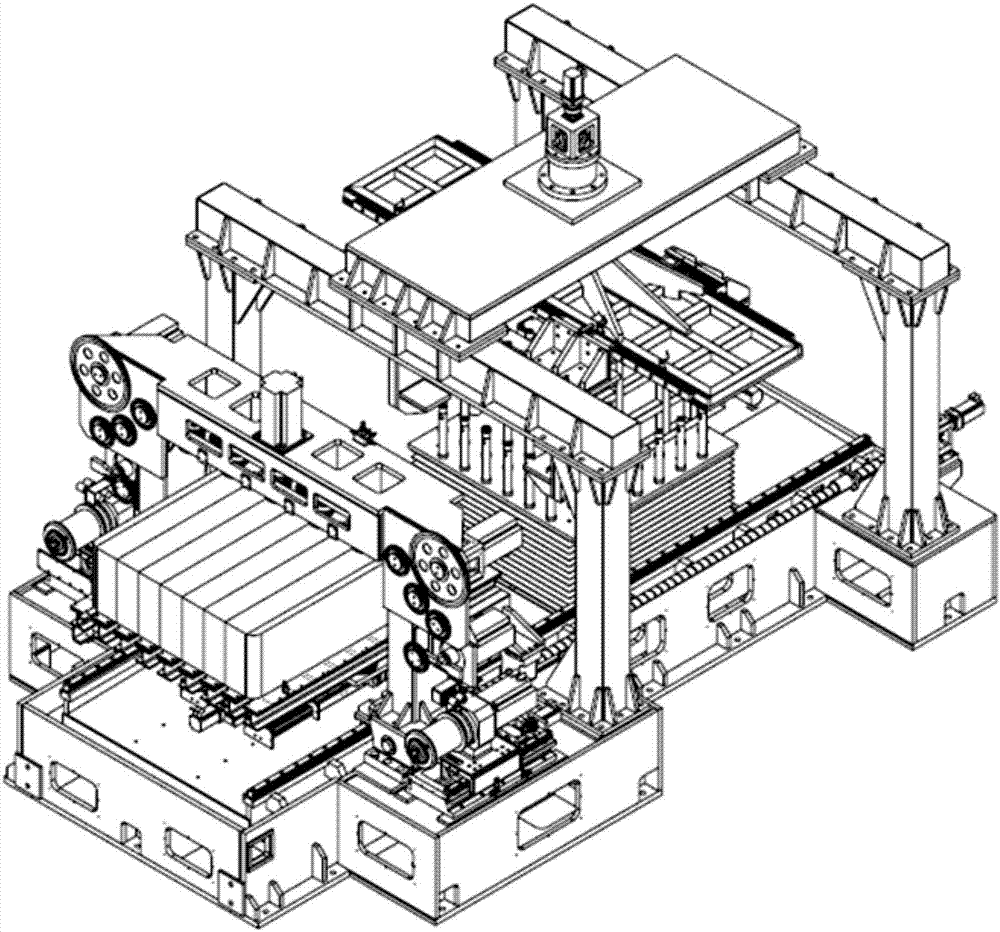
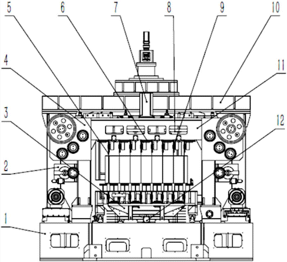
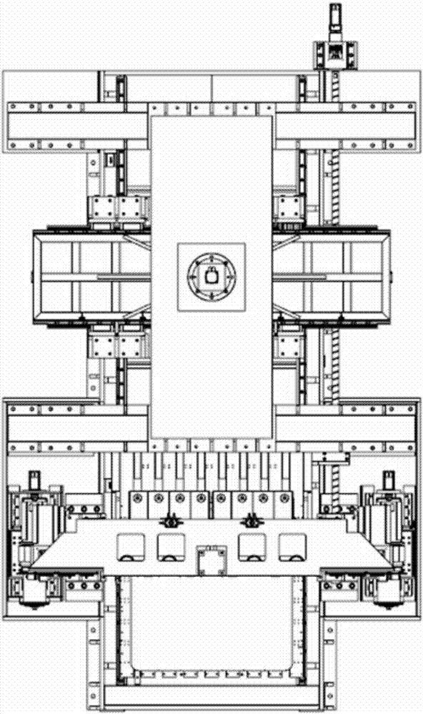
[0035] Such as Figure 1 to Figure 4 The shown diamond wire crystal ingot squarer includes a large chassis 1, a workbench 27, a workbench horizontal movement motor 13, a reducer 14, a main screw 15, a manipulator part 10, a cutting chamber part 4, a lifting mechanism 16, a retractor The wire releasing part 25 , the tension part 2 , and the bottom guide wheel part 3 can utilize the diamond wire 5 to cut the crystal ingot 26 .

[0036] Main rail 28 is housed on the described big chassis 1, and workbench 27 is housed above the main rail 28. The horizontal movement motor 13 of the workbench is installed on one side of the large chassis 1, the horizontal movement motor 13 of the workbench is connected with a speed reducer 14, and the speed reducer 14 is connected with the workbench 27 by the main screw 15, so that the workbench 27 can move along the...


PUM


Abstract

The invention relates to cutting equipment special for polycrystalline silicon processing and aims to provide a diamond wire crystal ingot squarer. The diamond wire crystal ingot squarer comprises a large bottom frame, a workbench, a workbench horizontal moving motor, a speed reducer, a main screw, a manipulator part, a cutting chamber part, a lifting mechanism, a take-up and payoff part, a tension part and a bottom guide wheel part. According to the diamond wire crystal ingot squarer, a diamond wire saw is adopted for cutting, a cutting mark is small, a cutting face is high in quality, material loss is reduced greatly, and the work environment is improved. According to the diamond wire crystal ingot squarer, a novel rotary mechanism is adopted for decreasing the height of the workbench, and thus the axis distance of a cutting guide wheel is reduced. The wire arch is small, cutter feeding is fast, the cutting efficiency is high, and the cutting dimensional deviation caused by a hard point is avoided. According to the diamond wire crystal ingot squarer, a horizontal moving function is added to a bottom guide wheel, a cutting line is changed into an oblique line from a vertical line during second time of cutter feeding, only a cutting-in opening is cut in the upper portion of a crystal ingot, and thus the uncontrollable size and edge breakage are avoided.

Description

technical field [0001] The invention relates to the field of special cutting equipment for polysilicon processing, in particular to a diamond wire crystal ingot squarer. Background technique [0002] After the polycrystalline silicon ingot is fired and shaped, it needs to go through processes such as squaring, truncating, grinding and chamfering, and slicing to make solar photovoltaic cells. The squaring of the crystal ingot is the first process in the overall processing process, which is to cut the large crystal ingot into small cuboids. At present, the most mature and common squaring equipment uses grid wires to cut from above. The working area of ​​wire saws is composed of several cutting lines perpendicular to each other and on different planes. No 4 wires form a grid. When the equipment is running, the cutting wire is driven to cut the silicon ingot. After the cutting is completed, a small rectangular parallelepiped crystal ingot is formed in the grid formed by the wir...

Claims


Application Information

Patent Timeline
Patent Type & Authority Patents(China)
IPC IPC(8): B28D5/04B28D5/00
CPCB28D5/0082B28D5/045
Inventor 曹建伟沈文杰傅林坚卢嘉彬何守龙邱文杰杨思炜沈加富邱敏秀
Owner ZHEJIANG JINGSHENG MECHANICAL & ELECTRICAL
Why Eureka
Try Eureka