A method for removing carbon from high-carbon copper-containing hot metal by injecting CO2
A technology of CO2 and molten iron, applied in the field of metallurgy, can solve the problems of no decarbonization and copper preservation, and achieve the effects of low cost, high environmental protection, and reduced smoke and dust emissions
- Summary
- Abstract
- Description
- Claims
- Application Information
AI Technical Summary
Problems solved by technology
Method used
Image
Examples
Embodiment 1
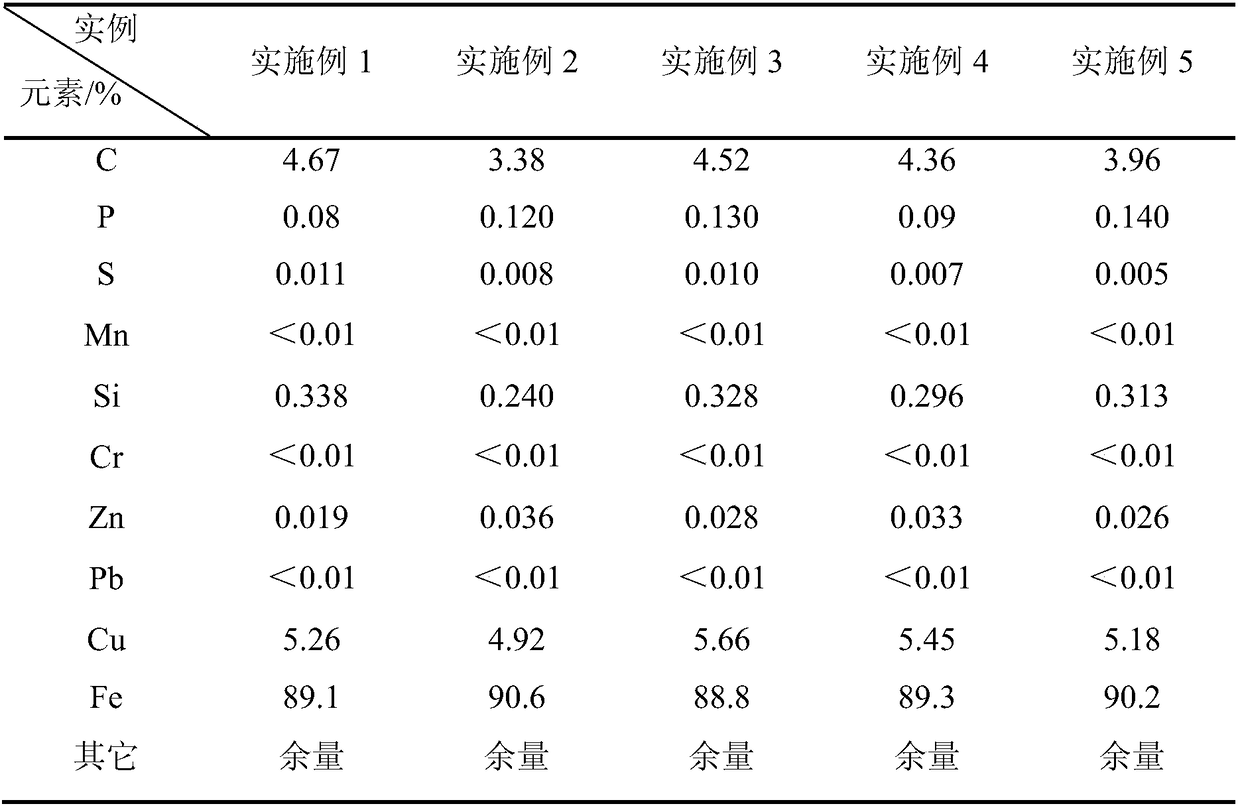
[0037] The high-carbon copper-containing molten iron used in the embodiment of the present invention is shown in Table 1 for the analysis results of elements in the high-carbon copper-containing molten iron.
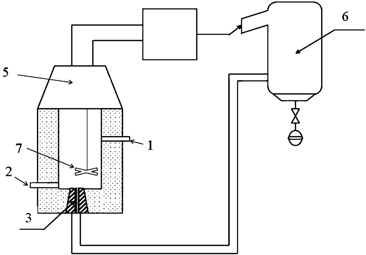
[0038] The structural schematic diagram of the induction furnace system adopted in this embodiment is shown in figure 1 .
[0039] A blown CO 2 The method for removing carbon from high-carbon copper-containing molten iron comprises the following steps:
[0040] (1) 20t reduced molten high-carbon copper-containing molten iron is introduced from the launder figure 1 In the induction furnace shown, the temperature of the high-carbon copper-containing molten iron is 1500°C by heating the induction furnace;
[0041] (2) Insert the stirring paddle 7 to 1 / 3 of the height of the liquid level of the copper-containing molten iron through the stirring paddle lifting system, and carry out eccentric stirring, wherein the eccentricity is 0.1, and the stirring speed is 50r / min; mean...
Embodiment 2
[0047] The high-carbon copper-containing molten iron used in the embodiment of the present invention is shown in Table 1 for the analysis results of elements in the high-carbon copper-containing molten iron.
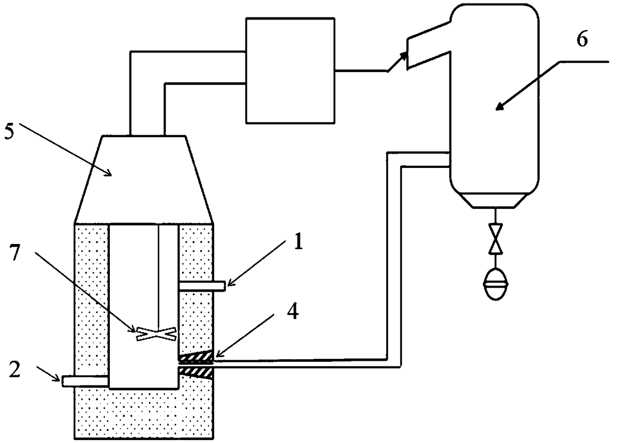
[0048] The structural schematic diagram of the induction furnace system adopted in this embodiment is shown in figure 2 .
[0049] A blown CO 2 The method for removing carbon from high-carbon copper-containing molten iron comprises the following steps:
[0050] (1) 30t reduced molten high-carbon copper-containing molten iron is introduced from the launder figure 2 In the induction furnace shown, the temperature of the high-carbon copper-containing molten iron is 1500°C by heating the induction furnace;
[0051] (2) Insert the stirring paddle 7 into the 1 / 2 place of the liquid level height of the copper-containing molten iron through the stirring paddle lifting system, and carry out eccentric stirring, wherein the eccentricity is 0.4, and the stirring speed is 100r / m...
Embodiment 3
[0056] The high-carbon copper-containing molten iron used in the embodiment of the present invention is shown in Table 1 for the analysis results of elements in the high-carbon copper-containing molten iron.
[0057] The structural schematic diagram of the induction furnace system adopted in this embodiment is shown in figure 2 .
[0058] A blown CO 2 The method for removing carbon from high-carbon copper-containing molten iron comprises the following steps:
[0059] (1) 30t reduced molten high-carbon copper-containing molten iron is introduced from the launder figure 2 In the induction furnace shown, the temperature of the high-carbon copper-containing molten iron is 1450°C through induction furnace heating;
[0060] (2) Insert the stirring paddle 7 to the 1 / 2 place of the liquid level height of the copper-containing molten iron through the stirring paddle lifting system, and carry out eccentric stirring, wherein, the eccentricity is 0.5, and the stirring speed is 100r / m...
PUM
 Abstract
Description
Claims
Application Information
 - R&D
- Intellectual Property
- Life Sciences
- Materials
- Tech Scout
- Unparalleled Data Quality
- Higher Quality Content
- 60% Fewer Hallucinations
Browse by: Latest US Patents, China's latest patents, Technical Efficacy Thesaurus, Application Domain, Technology Topic, Popular Technical Reports.
© 2025 PatSnap. All rights reserved.Legal|Privacy policy|Modern Slavery Act Transparency Statement|Sitemap|About US| Contact US: help@patsnap.com


