Observation method of soil body shear zone expansive process

An extended process and shear band technology, applied in the field of geotechnical engineering, can solve the problems of cumbersome test process, complex device structure, and high test cost

Active Publication Date: 2016-12-07
XIAN UNIV OF SCI & TECH
View PDF13 Cites 6 Cited by
  • Summary
  • Abstract
  • Description
  • Claims
  • Application Information

AI Technical Summary

Problems solved by technology

Existing observation methods for the expansion process of soil shear bands have problems such as complex device structure, high test cost, cumbersome test process, poor operability, and poor use effect to varying degrees. The most important thing is that they cannot be simple, fast and accurate. Analyzing the soil microstructure of the shear zone, it is impossible to understand the influence of the soil microstructure on the macroscopic performance of the soil shear zone, and it is impossible to establish the relationship between the soil microstructure characteristics of the soil shear zone and its macroscopic performance. contact

Method used


Image

  • Observation method of soil body shear zone expansive process
  • Observation method of soil body shear zone expansive process
  • Observation method of soil body shear zone expansive process

Examples


Embodiment 1

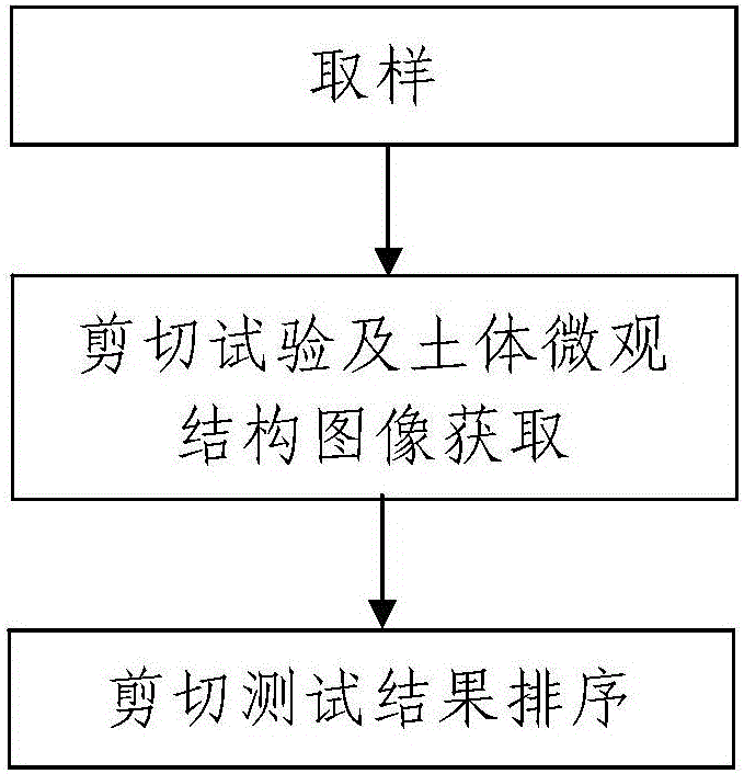
[0088] Such as figure 1 A method for observing the expansion process of a soil shear band includes the following steps:

[0089] Step 1. Sampling: using the sampling ring knife 2 to cut the tested soil samples 1 from a plurality of different depths in the shear zone of the soil to be tested, and record the soil sampling depth of each tested soil sample 1;

[0090] The tested soil sample 1 is cylindrical and its upper and lower surfaces are plane;

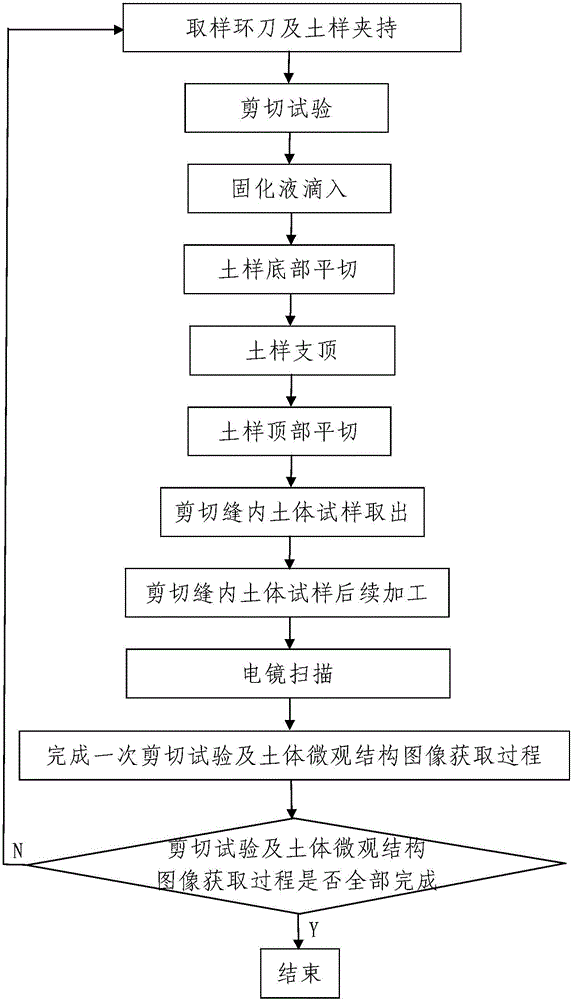
[0091] Step 2. Shear test and soil microstructure image acquisition: perform shear test and soil microstructure respectively on the tested soil samples 1 at multiple different depths in the shear zone of the soil to be tested taken in step 1. Image acquisition; where, such as Picture 1-1 As shown, when any one of the tested soil samples 1 is subjected to a shear test and soil microstructure image acquisition, the process is as follows:

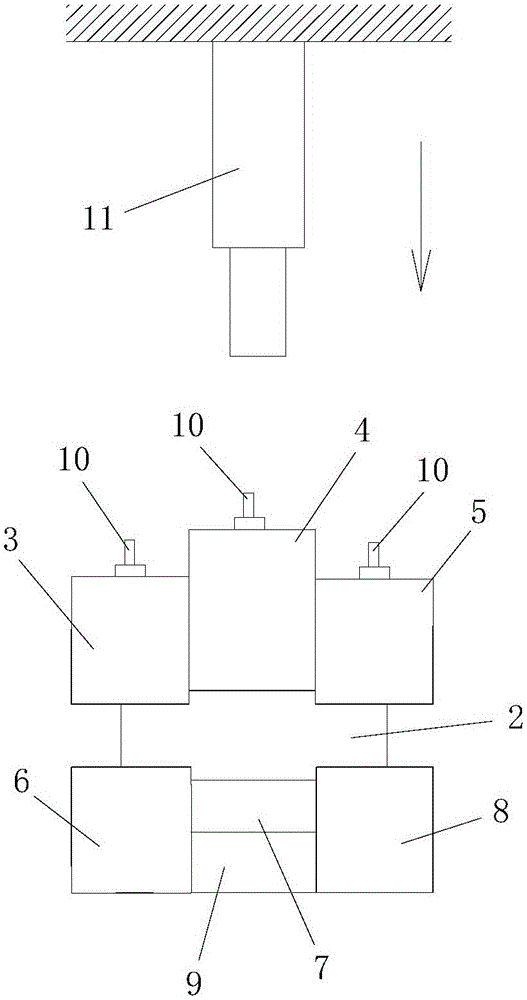
[0092] Step 201, sampling ring knife and soil sample clamping: the sampling ring knife 2 con...

Embodiment 2

[0196] Such as Figure 5 As shown, in this embodiment, the difference from Embodiment 1 is that the shearing jig in step 201 further includes a limiting sleeve 12 fitted on the upper jig and outside the lower jig.

[0197] In this embodiment, the remaining method steps are the same as those in Embodiment 1.

Embodiment 3

[0199] Such as Figure 6 , Figure 7 As shown, in this embodiment, the difference from Embodiment 1 is that the widths of the upper clamp and the lower clamp in step 201 are the same as the inner diameter of the earth taking ring cutter 2; the middle and lower clamping blocks only include Upper clamping block 7; the length, width and height of the upper left clamping block 3, the upper right clamping block 5, the lower left clamping block 6 and the lower right clamping block 8 are all the same, and the middle and upper clamping blocks 4 and The width and height of upper clamping block 7 are all identical with left upper clamping block 3, and the length of described middle upper clamping block 4 and upper clamping block 7 is identical and the length of both is greater than the length of left upper clamping block 3.

[0200] During actual processing, the lengths of the upper left clamping block 3, the upper right clamping block 5, the upper middle clamping block 4, the lower le...


PUM

PropertyMeasurementUnit
heightaaaaaaaaaa

Abstract

The invention discloses an observation method of a soil body shear zone expansive process. The observation method includes the steps of: 1) sampling: cutting to-be-tested soil samples from a to-be-tested soil body shear zone at different depths by means of a sampling cutting ring; 2) performing shear test and obtaining soil body micro-structural images, wherein a shear test result of the to-be-tested soil samples from the to-be-tested soil body shear zone at different depths is obtained, and the step 2) includes the processes of: clamping the sampling cutting ring and the soil sample, performing the shear test, dropwise adding a curing liquid, level-cutting the bottom of the soil sample, supporting the soil sample, level-cutting the top of the soil sample, taking the soil sample out from a shear seam, subsequently processing the soil sample in the shear seam, and performing electron microscope scanning; 3) sequencing the shear test result. The method has reasonable design and simple operations, is good in use effects, can easily obtain the shear strength of different depths and the micro-structure of the shear positions of the soil body shear zone so as to perform simple and direct observation of the soil body shear zone expansive process.

Description

technical field [0001] The invention belongs to the technical field of geotechnical engineering, and in particular relates to an observation method for the expansion process of a soil shear zone. Background technique [0002] In recent years, the transformation of the natural environment by human activities has become more and more intense. Human engineering activities have caused many geological disasters, which have caused great damage to people's lives and property. Among them, the slope instability induced by human activities is the most serious, and the focus of the study of slope instability is to study the deformation and expansion process of the soil shear zone. The shear zone refers to a strong deformation zone with shear strain developed in the lithosphere or soil mass, and the shear zone developed in the soil mass is a soil shear zone. This deformation zone can be a planar structure (fault) with strain discontinuity, or a ductile shear zone with continuous strai...

Claims


Application Information

Patent Timeline
Patent Type & Authority Applications(China)
IPC IPC(8): G01N3/24G01N3/04G01N3/06
CPCG01N3/04G01N3/066G01N3/24G01N2203/0617G01N2203/04G01N2203/0025G01N2203/0048G01N2203/0066
Inventor 李晓军李昊
Owner XIAN UNIV OF SCI & TECH
Why Eureka
Try Eureka