Passive type MEMS flow-induced vibration strengthened heat transfer apparatus and heat transfer method

An enhanced heat transfer and passive technology, applied in microstructure devices, microstructure devices composed of deformable elements, piezoelectric devices/electrostrictive devices, etc. Heat dissipation performance, complex overall structure and other issues, to achieve the effect of simple structure, avoiding material separation, and good heat dissipation effect

Active Publication Date: 2016-12-07
ZHEJIANG UNIV
View PDF8 Cites 19 Cited by
  • Summary
  • Abstract
  • Description
  • Claims
  • Application Information

AI Technical Summary

Problems solved by technology

The traditional passive heat dissipation technology represented by increasing the heat transfer area has been difficult to improve its heat dissipation performance under the constraints of the miniaturization of the packaging size of modern electronic devices. However, the new generation of passive heat dissipation technologies such as water cooling and phase change have a relatively Complex, difficult to apply to tiny electronic devices
As for active enhanced heat transfer technologies such as synthetic jets and mechanical disturbances, their structures are also relatively complex, and additional energy needs to be consumed during the heat dissipation process.

Method used


Image

  • Passive type MEMS flow-induced vibration strengthened heat transfer apparatus and heat transfer method
  • Passive type MEMS flow-induced vibration strengthened heat transfer apparatus and heat transfer method
  • Passive type MEMS flow-induced vibration strengthened heat transfer apparatus and heat transfer method

Examples


Embodiment Construction

[0015] The present invention will be further described below in conjunction with the drawings and embodiments.

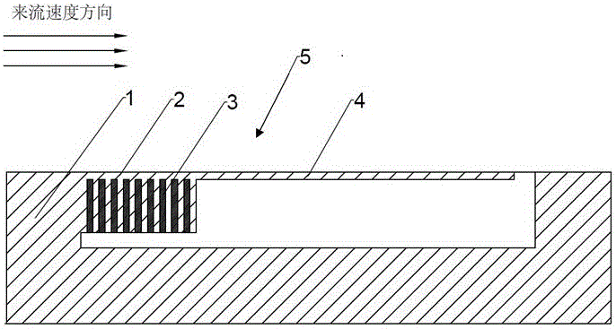
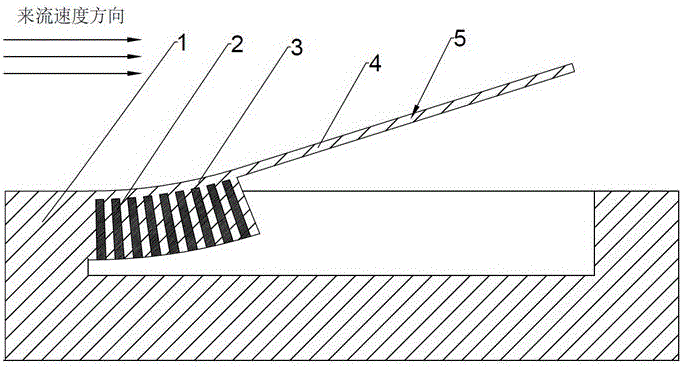
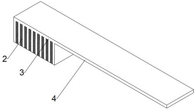
[0016] Such as figure 1 As shown, a passive temperature-controlled MEMS flow-induced vibration-enhanced heat transfer device includes a heat sink base 1, a filling material 2, a comb-shaped structure 3, and a vibration part 4; the heat sink base 1 and the heating of electronic devices Part of it is connected by a heat pipe, which can absorb the heat emitted by the electronic device and increase its temperature; the driving part is composed of a comb-like structure 3 and a filling material 2 filled between the teeth (usually a thermal expansion coefficient greater than 1x10 -5 / K The comb-tooth structure 3 is connected to the heat sink base 1; the vibrating part 4 is an extension of the top thin layer of the comb-tooth structure 3, which forms the MEMS flow together with the comb-tooth structure 3 and the filling material 2. The cantilever beam structure 5 of the vibrat...


PUM


Abstract

The invention discloses a passive type MEMS flow-induced vibration strengthened heat transfer apparatus and heat transfer method. Through reasonable structural design, a cantilever beam structure fixed on a heat sink can generate a deflection movement far from the heat sink when the temperature of the heat sink increases, and the deflection angle is enlarged along with the increasing of the heat sink temperature. When the deflection angle of the cantilever beam structure is enlarged, an included angle between the length direction and an inflow velocity direction is correspondingly enlarged, so that the vibration of the cantilever beam vibration part is more fierce; therefore, higher disturbance is brought to a flow field close to the cantilever beam, formation of a heat boundary layer is damaged, and strengthened heat transfer is realized finally; the strengthened heat transfer apparatus does not require manual control and external energy input; and instead, the heat dissipation intensity can be adjusted automatically according to the heat sink temperature, so that a new approach is provided to solve a high heat flux problem of modern electronic devices.

Description

Technical field [0001] The invention relates to a passive temperature-controlled MEMS flow-induced vibration enhanced heat transfer device and a working method thereof, which can be widely used in the field of heat dissipation of modern electronic devices. Background technique [0002] Electronic devices have penetrated into every corner of modern life and play a huge role in many technical fields. With the further development of technology, people have higher and higher performance requirements for electronic devices, presenting a development trend of high performance and small size. This development trend makes the thermal design of electronic devices more and more important. The traditional passive heat dissipation technology represented by increasing the heat transfer area has been difficult to improve its heat dissipation performance under the constraints of the miniaturization of modern electronic device packaging sizes. The new generation of passive heat dissipation techno...

Claims


Application Information

Patent Timeline
Patent Type & Authority Applications(China)
IPC IPC(8): H01L23/367B81B3/00
CPCH01L23/3672B81B3/0024
Inventor 吴昌聚邱云龙陈伟芳
Owner ZHEJIANG UNIV
Why Eureka
Try Eureka