Permanent magnet brushless direct current motor digital speed regulator

A permanent magnet brushless DC, digital governor technology, applied in the direction of single motor speed/torque control, etc., to achieve the effect of reducing manufacturing costs, overall optimization, and system saving

Active Publication Date: 2016-12-07
彭希南
View PDF7 Cites 9 Cited by
  • Summary
  • Abstract
  • Description
  • Claims
  • Application Information

AI Technical Summary

Problems solved by technology

Faced with so many application requirements, it is obvious that speed-adjustable drive equipment is required to match it. However, the existing permanent magnet brushless DC motor control devices are basically aimed at the electric bicycle and new energy electric vehicle industries, and there is no general-purpose one. Permanent magnet brushless DC motor speed control equipment to meet the needs of all walks of life, based on this reason, the present invention proposes a permanent magnet brushless DC motor digital speed governor, the biggest feature of the speed governor is that it has The control function of the permanent magnet brushless DC motor also has the indication function of its speed, and more importantly, it can be directly started, adjusted and stopped on the governor, especially its embedded installation design, which is simple The installation and use mode can meet the speed regulation control requirements of different products and different application requirements

Method used


Image

  • Permanent magnet brushless direct current motor digital speed regulator
  • Permanent magnet brushless direct current motor digital speed regulator
  • Permanent magnet brushless direct current motor digital speed regulator

Examples


Embodiment Construction

[0052] The present invention as Figure 1 to Figure 10 shown.

[0053] The specific embodiment of the present invention is illustrated below in conjunction with accompanying drawing:

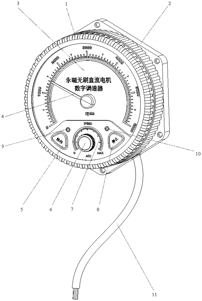
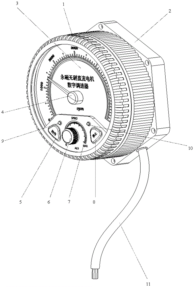
[0054] Permanent magnet brushless DC motor digital speed controller, including upper housing end cover (1), middle frame, lower housing end cover (2), hexahedron cover plate (19), speed indicating dial (3), pointer (4 ), control cable (11), PCB board (20), triple-core microcontroller (23), signal conditioning chip (24), electrolytic capacitor bank (22), VMOS tube driver chip (32), VMOS tube (21), A micro stepper motor (29), characterized in that:

[0055] The end cover (1) of the upper housing is equipped with a steering button (5), a stop button (8), a steering indicator light-emitting diode (9), a stop indicator light-emitting diode (10), a speed control knob (6) and a The speed dial (7), the inner thread of the upper case end cap (1) is provided on the inner side of the upper case end cap ...


PUM


Abstract

The invention provides a permanent magnet brushless direct current motor digital speed regulator. The permanent magnet brushless direct current motor digital speed regulator comprises an upper shell end cover, a middle frame, a lower shell end cover, a rotating speed indicating dial plate, a pointer, a PCB, a three-core single-chip microcomputer, a signal conditioning chip, a VMOS transistor drive chip, a VMOS transistor and a micro-stepping motor. The permanent magnet brushless direct current motor digital speed regulator is characterized in that a steering button, a stop button, a steering indicating light-emitting diode, a stopping indicating light-emitting diode, a speed regulating rotary knob and a speed regulating dial are mounted on the upper shell end cover; rotating speed numerical scales are carved in the rotating speed indicating dial plate, the middle frame is made of aluminum alloy and composed of a middle frame hollow cylinder and a middle frame cylinder hexahedron, and the middle frame hollow cylinder and the middle frame cylinder hexahedron are combined through six connecting lugs; the upper shell end cover and the lower shell cover are connected with the middle frame cylinder, a rotary shaft of the micro-stepping motor is externally connected with the pointer, and under control of the three-core single-chip microcomputer, the position, on the rotating speed numerical scales, of the pointer is the current rotating speed of a permanent magnet brushless direct current motor.

Description

technical field [0001] The invention relates to a permanent magnet brushless DC motor digital speed controller, which is mainly used in the fields of household appliances, flexible manufacturing systems, new medical equipment and industrial automatic control equipment. Background technique [0002] Permanent magnet brushless DC motor is a brushless and mechanical commutator DC motor that can be started with stepless speed regulation. It has stable operation, low noise, and large starting torque. It is powered by DC or AC / DC conversion and hardly Affected by grid voltage fluctuations, it has a wide range of speed regulation and a wide range of operating speeds, which can meet the speed requirements of various operating modes, and can maintain output torque at ultra-low speeds. The energy-saving effect is good, and many In one aspect, it has surpassed the performance of the AC frequency converter and can completely replace the low-power AC frequency conversion speed regulati...

Claims


Application Information

Patent Timeline
Patent Type & Authority Applications(China)
IPC IPC(8): H02P6/08
CPCH02P6/08
Inventor 彭希南
Owner 彭希南
Why Eureka
Try Eureka