
A method of manufacturing a return plate of a plunger pump

A manufacturing method and a return plate technology, applied in metal processing equipment, transportation and packaging, etc., can solve the problems of low material utilization rate, low production efficiency, complicated process, etc., achieve simple process, increase production efficiency, and improve production efficiency Effect

Active Publication Date: 2018-05-22
合肥波林新材料股份有限公司
View PDF10 Cites 0 Cited by
  • Summary
  • Abstract
  • Description
  • Claims
  • Application Information

AI Technical Summary

Problems solved by technology

In the prior art, machining and die forging are mostly used for manufacturing return discs. For example, the Chinese patent document with application number 201510725216.9 discloses a manufacturing method for forming return discs by closed die forging; for example, application number 201110269432.9 The Chinese patent document discloses a manufacturing method of forming a return plate by cold heading stamping of 42CrMo steel; in the prior art, the return plate is formed by machining or die forging, which has low material utilization rate, complicated process, and low production efficiency. question

Method used


Image

  • A method of manufacturing a return plate of a plunger pump

Examples


Embodiment 1-2

[0022] A method for manufacturing a return plate of a plunger pump, comprising the following steps:

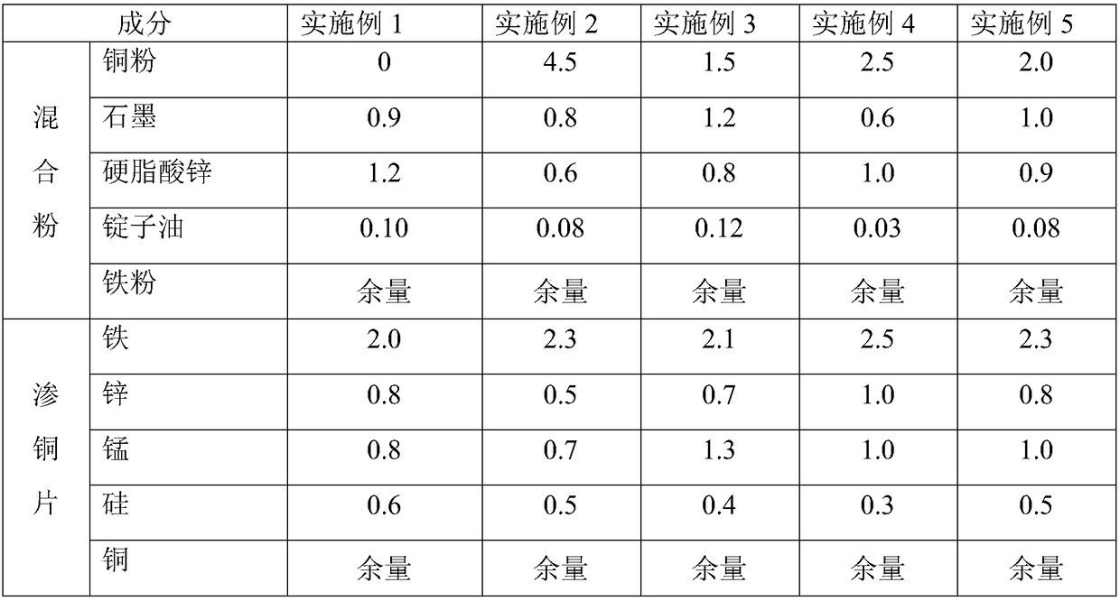
[0023] Mixing: Weigh each raw material according to the weight percentage of each component in Table 1. Iron powder is reduced iron powder; add spindle oil to iron powder, mix for 20-200 minutes to form oil-containing iron powder, and then mix oil-containing iron powder, stearic acid Zinc and graphite are added to the mixer and mixed. The grade of graphite is 299, and the copper powder is electrolytic copper powder. After mixing evenly, take it out to obtain the mixed powder;

[0024] Press the green compact: Install the return disc mold on the press, put the mixed powder into the cavity of the mold, and press the mixed powder into a return disc compact with a compact density of 6.6-6.9g / cm 3 ;

[0025] Copper infiltrating sintering: Place the copper infiltrating sheet above the compact of the return plate, and carry out copper infiltrating sintering in a protective atmospher...

Embodiment 3-5

[0030] The difference from Example 1-2 is that in the mixing step, the grade of graphite is 399; the iron powder is atomized iron powder. The manufactured return disk was tested for performance, and the results are shown in Table 2.

[0031] Table 1 return plate embodiment 1-5 proportioning table (wt%)

[0032]

[0033] Table 2 The performance test results of the return disk prepared in Example 1-5

[0034] performance

[0035] The running time of the installation test of the return disk made by the present invention is more than 300 hours, which fully meets the working conditions.


PUM

PropertyMeasurementUnit
densityaaaaaaaaaa
densityaaaaaaaaaa
densityaaaaaaaaaa

Abstract

The invention discloses a method for manufacturing a return plate of a plunger pump, which belongs to the field of plunger pump parts and includes the following steps: weighing each raw material according to the weight percentage content: adding spindle oil to iron powder, mixing evenly to form oil-containing iron powder, and then Add oil-containing iron powder, copper powder, zinc stearate, and graphite into the mixer and mix evenly to obtain mixed powder; install the return plate mold on the press, fill the mixed powder into the mold cavity, and press the mixed powder into Return disc compact; place the copper infiltrated sheet on the return disc compact, carry out copper infiltration sintering to form a sintered billet; deburr, and machine into the finished product of the plunger pump return disc. The invention reduces the segregation of graphite and increases the uniformity of the mixed powder by adding spindle oil to the iron powder; the copper infiltrating sintering of the present invention makes the material have good toughness and anti-seizing performance; it adopts mixing, compacting and copper infiltrating sintering, etc. The production process is simple, the material utilization rate is increased, the production efficiency is high, and the production efficiency is improved.

Description

technical field [0001] The invention belongs to the field of hydraulic products of high-pressure plunger pumps, in particular to a method for manufacturing a plunger pump return plate. Background technique [0002] The return plate is one of the key core parts of the axial piston hydraulic pump. It forms a return device together with the return spring and the ball joint when the plunger pump sucks oil, and presses the sliding shoe tightly against the surface of the swash plate to slide. In the prior art, machining and die forging are mostly used for manufacturing return discs. For example, the Chinese patent document with application number 201510725216.9 discloses a manufacturing method for forming return discs by closed die forging; for example, application number 201110269432.9 The Chinese patent document discloses a manufacturing method of forming a return plate by cold heading stamping of 42CrMo steel; in the prior art, the return plate is formed by machining or die for...

Claims


Application Information

Patent Timeline
Patent Type & Authority Patents(China)
IPC IPC(8): B22F1/00B22F3/02B22F3/10B22F3/24C22C38/16B22F5/00
CPCC22C38/16B22F3/02B22F3/1007B22F3/24B22F5/00B22F2003/023B22F2003/247B22F1/10
Inventor 汤浩张东李其龙张俊杰孙本松吴亚民
Owner 合肥波林新材料股份有限公司
Learn More