
Ultrasonic longitudinal torsion vibration machining device and machining process

A vibration processing and ultrasonic technology, applied in metal processing, fluid using vibration, etc., can solve problems such as increased system loss, low power transmission efficiency, limited application, etc., to improve processing quality and efficiency, meet the requirements of automatic tool change, Guarantee the effect of high-efficiency transmission

Inactive Publication Date: 2016-12-14
WUHAN UNIV OF TECH
View PDF10 Cites 24 Cited by
  • Summary
  • Abstract
  • Description
  • Claims
  • Application Information

AI Technical Summary

Problems solved by technology

[0003] The current ultrasonic vibration processing system mostly uses contact power transmission power supply. There is mechanical wear and friction between the power supply system and the load, which increases the loss of the system, and due to the existence of the brush, the rotation speed of the tool is limited, thereby limiting the processing quality. and efficiency
The non-contact power transmission method effectively solves the above problems, but the non-contact power transmission method has high requirements on the parameters such as the core gap of the primary and secondary windings, and the power transmission efficiency is low, which limits the application of this method

Method used


Image

  • Ultrasonic longitudinal torsion vibration machining device and machining process
  • Ultrasonic longitudinal torsion vibration machining device and machining process
  • Ultrasonic longitudinal torsion vibration machining device and machining process

Examples


Embodiment Construction

[0030] In order to better understand the present invention, the present invention will be further described below in conjunction with the accompanying drawings and specific embodiments.

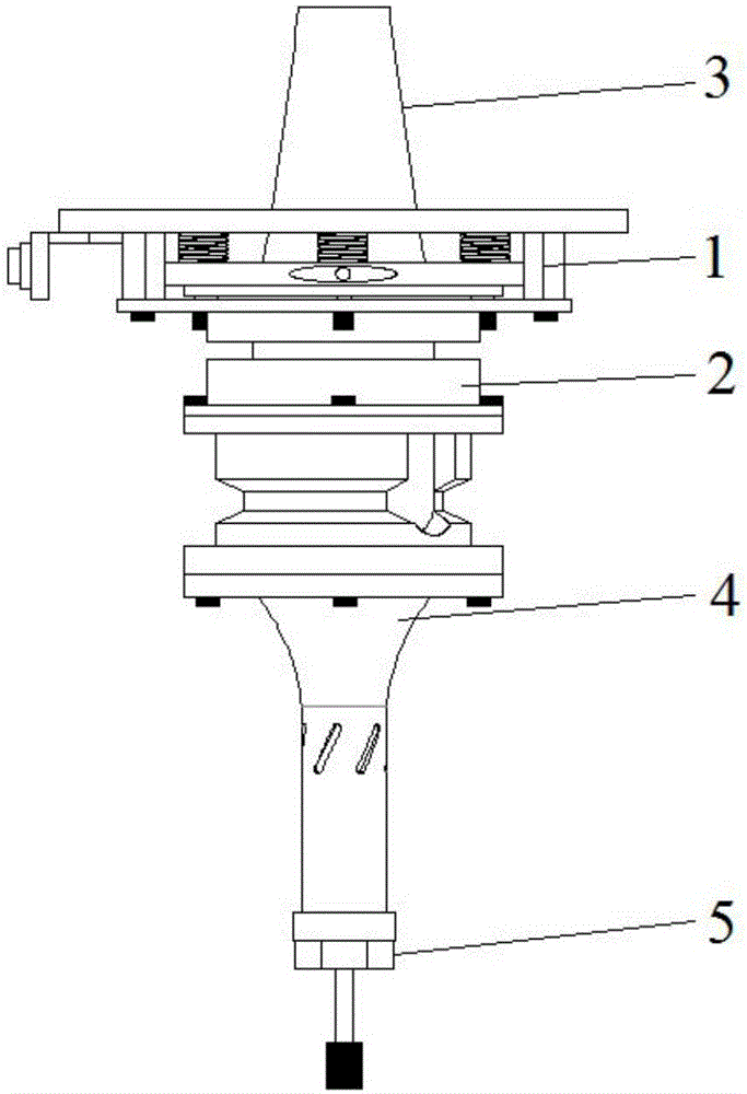
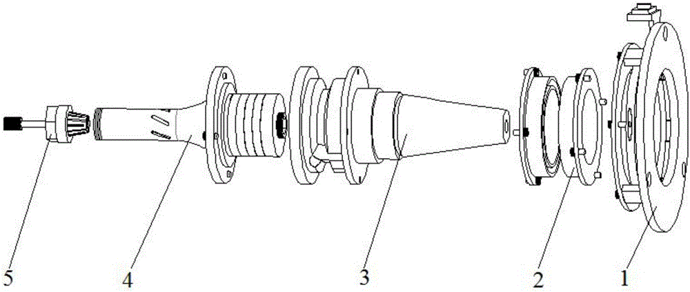
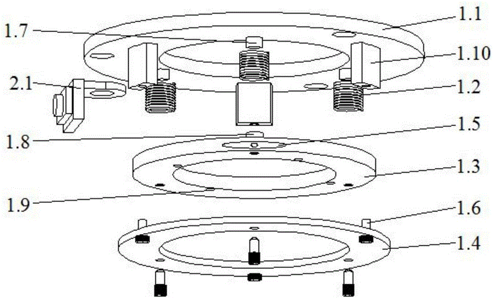
[0031] Such as figure 2 An ultrasonic longitudinal-torsional vibration processing device shown includes a non-contact energy transmission component 2, a tool handle component 3, a transducer component 4, and a tool component 5, wherein the non-contact energy transmission component 2 includes a power supply box 2.1, a primary side Coil, primary magnetic core, secondary coil 2.2 and secondary magnetic core, one end of the power supply box 2.1 is connected to the ultrasonic power supply (not shown in the drawings), the other end of the power supply box 2.1 is electrically connected to the primary coil, and the primary coil is wound On the primary side magnetic core, the secondary side coil 2.2 is wound on the secondary side magnetic core, the primary side coil corresponds to the secondary side ...


PUM


Abstract

The invention discloses an ultrasonic longitudinal torsion vibration machining device. The device comprises a shank module, a transducer module, a cutter module and a non-contact energy transmission module; the shank module includes an upper shaft connected with a machine tool main shaft, and a hollow lower shaft; the upper shaft and the lower shaft rotate along with the machine tool main shaft; the transducer module includes a piezoelectric ceramic wafer mounted in the lower shaft, and a variable amplitude rod fixedly connected to the lower end of the lower shaft; the cutter module is fixed at the lower end of the variable amplitude rod; and the piezoelectric ceramic wafer is connected with an electric energy output end of the non-contact energy transmission module. The invention further provides an ultrasonic longitudinal torsion vibration machining process. The ultrasonic longitudinal torsion vibration machining device and the machining process have the following beneficial effects that (1) an adjusting module is adopted to adjust a magnetic gap between primary and secondary coils and the axis deflection, so that the high-efficiency transmission of electric energy is guaranteed, and the machining quality and efficiency are improved; and (2) the non-contact energy transmission design is adopted to solve the energy consumption by the slide ring wear in traditional ultrasonic machining.

Description

technical field [0001] The invention relates to the technical field of ultrasonic processing equipment, in particular to an ultrasonic longitudinal torsional vibration processing device and a processing technology. Background technique [0002] Composite materials such as carbon fiber have excellent properties such as high strength, high temperature resistance, wear resistance and corrosion resistance, and have been widely used in machinery, electronics, aviation, automobiles and other fields. However, it is these characteristics that increase the processing difficulty of composite materials such as carbon fiber. Traditional processing methods have low processing efficiency and high cost, which limits the further application of composite materials such as carbon fiber. With the development of science and technology, special processing came into being and developed rapidly. [0003] The current ultrasonic vibration processing system mostly adopts contact power transmission p...

Claims


Application Information

Patent Timeline
Patent Type & Authority Applications(China)
IPC IPC(8): B26D1/12B26D7/08B06B1/06B06B3/02
CPCB06B1/06B06B3/02B26D1/12B26D7/086
Inventor 陈涛方亮叶梦力刘树良
Owner WUHAN UNIV OF TECH
Learn More