Solar heat energy power system based on honeycomb cavity gasification

A solar thermal energy and power system technology, which is applied to machines/engines, steam engine devices, mechanical equipment, etc., can solve the problems of small external waste heat absorption rate, small amount of work, poor heat collection effect of heat collectors, etc. Gasification efficiency and condensation efficiency, stable gasification temperature and working fluid flow rate, and the effect of solar power output

Inactive Publication Date: 2016-12-14
郭远军
View PDF0 Cites 1 Cited by
  • Summary
  • Abstract
  • Description
  • Claims
  • Application Information

AI Technical Summary

Problems solved by technology

[0007] However, the common problems of existing thermal power generation equipment are: a. The temperature requirements for high-temperature heat sources are high, generally above 200°C, and the thermal energy conversion efficiency is low. The thermal energy conversion efficiency is generally 15% to 35%. Under the heat source of ℃, the average thermal energy conversion efficiency is 18%; b. The gasification of the working fluid in the gasification device is prone to incomplete gasification, the volume expansion is small, and the amount of external work in a single cycle of the gasification process is small; c. The gasification temperature is unstable, the condensation effect of the working medium is not good, and the working medium is easy to deteriorate or appear impurities; d. The driving force of the turbine is small, and the efficiency of converting the external work of the gasification medium into mechanical energy is low; e. The speed of the turbine is unstable, and It is prone to stuck problems; f. The heat collection effect of the heat collection device is not good, and the external waste heat absorption rate is small; g. The heat displacement of the condensing device is large, and the heat energy is wasted. The condensation speed through natural condensation is slow, and the use of Active condensation mode (fan air cooling or liquid pump water cooling) requires additional power consumption
[0008] In the process of realizing the power output of existing solar energy, the photoelectric effect is first required to convert it into electrical energy, and then output power through electric equipment; at this stage, the equipment used to convert solar energy into electrical energy is mainly a photovoltaic panel. At about 5%, energy waste is serious

Method used


Image

  • Solar heat energy power system based on honeycomb cavity gasification
  • Solar heat energy power system based on honeycomb cavity gasification
  • Solar heat energy power system based on honeycomb cavity gasification

Examples


Embodiment 1

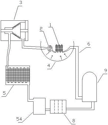
[0078] Embodiment one (such as figure 1 shown): a solar thermal energy power system based on honeycomb cavity gasification, including a heat collector 1, a gasification device 2, a turbine 3, a solar concentrating cover 4, a condensation device 5, a circulation pipeline 6, a circulating working medium 7 and The one-way hydraulic pump 9, the heat collecting device 1, the gasification device 2, the turbine 3, the condensing device 5 and the one-way hydraulic pump 9 realize circulation communication through the circulation pipeline 6 in sequence, and the circulation pipeline 6 contains a circulating working medium 7;

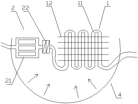
[0079] (Such as figure 2 As shown), the heat collecting device 1 and the gasification device 2 are installed in the solar concentrating cover 4, and the heat collecting device 1 includes solar heat collecting tubes 11 and solar heat collecting fins 12, and the solar heat collecting fins 12 are distributed in parallel at intervals, and the solar energy The heat co...

Embodiment 2

[0090] Embodiment two (such as Figure 9 shown): The difference from Embodiment 1 is that the solar heat collecting sheet 12 is in the shape of a curved sheet.

[0091] Through experiments on the solar thermal energy power system based on the gasification of the honeycomb cavity in the above-mentioned embodiment 2, the gasification temperature of the working fluid reaches 50°C, 55°C, 60°C, 65°C, 70°C respectively under different intensities of sunlight irradiation. ℃, when the temperature of the cold source is 18 ℃, the flow rate of the working medium in the circulation pipe is adjusted according to the operation stability of the solar thermal energy power system based on the gasification of the honeycomb cavity; the experimental results are: when the gasification temperature of the working medium is about 50 ℃ , the thermal energy conversion efficiency is about 17.5%. When the gasification temperature of the working fluid is about 55℃, the thermal energy conversion efficiency...

Embodiment 3

[0092] Embodiment three (such as Figure 10 shown): The difference from Embodiment 1 is that the solar heat collecting sheets 12 are distributed in a staggered manner.

[0093] Through experiments on the solar thermal energy power system based on honeycomb cavity gasification in the third embodiment above, the gasification temperature of the working fluid reaches 50°C, 55°C, 60°C, 65°C, and 70°C respectively under different intensities of sunlight irradiation. ℃, when the temperature of the cold source is 18 ℃, the flow rate of the working medium in the circulation pipe is adjusted according to the operation stability of the solar thermal energy power system based on the gasification of the honeycomb cavity; the experimental results are: when the gasification temperature of the working medium is about 50 ℃ , the thermal energy conversion efficiency is about 17.5%. When the gasification temperature of the working fluid is about 55℃, the thermal energy conversion efficiency is a...


PUM


Abstract

The invention discloses a solar heat energy power system based on honeycomb cavity gasification. The solar heat energy power system comprises a heat collection device, a gasification device, a turbine, a condensing device and a one-way hydraulic pump, all of which sequentially communicate with one another through a circulation pipeline. A circulation working medium is contained in the circulation pipeline. The heat collection device and the gasification device are installed in a solar light collecting cover. The condensing device is installed outside the solar light collecting cover. The gasification device comprises a solar gasification heat absorption cavity which is a cavity for gasifying the working medium in the gasification device. The gasification device is located in a heat collection cavity. The solar gasification heat absorption cavity is in a honeycomb cavity shape. The solar heat energy power system based on honeycomb cavity gasification has the beneficial effects of being high in gasification efficiency, high in heat energy conversion efficiency, adjustable in power and the like.

Description

technical field [0001] The invention belongs to the field of energy utilization equipment, in particular to a solar thermal energy power system based on honeycomb cavity gasification. Background technique [0002] Energy is an important material basis for the survival and development of human society. Throughout the history of the development of human society, every major progress of human civilization is accompanied by the improvement and replacement of energy. The development and utilization of energy has greatly promoted the development of the world economy and human society. [0003] However, with the continuous development and consumption of energy, non-renewable energy sources such as petroleum, coal mines, and natural gas are gradually reduced, and energy conservation and recycling are gradually being valued. The basic content of my country's current energy strategy is: adhere to the priority of conservation, based on domestic, diversified development, rely on scien...

Claims


Application Information

Patent Timeline
Patent Type & Authority Applications(China)
IPC IPC(8): F01K11/02F01K27/02
CPCF01K11/02F01K27/02
Inventor 郭远军
Owner 郭远军
Why Eureka
Try Eureka