
Pentaprism scanning detection method for aspheric reflector

A technology of scanning detection and pentaprism, which is applied in the direction of measuring devices, optical devices, instruments, etc., can solve the problems of low surface accuracy, large deviation, and lack of interference fringes on the surface of the mirror, and meet the detection range and Accuracy requirements, large measurement dynamic range, and the effect of on-site detection

Inactive Publication Date: 2016-12-14
CHANGCHUN INST OF OPTICS FINE MECHANICS & PHYSICS CHINESE ACAD OF SCI
View PDF1 Cites 11 Cited by
  • Summary
  • Abstract
  • Description
  • Claims
  • Application Information

AI Technical Summary

Problems solved by technology

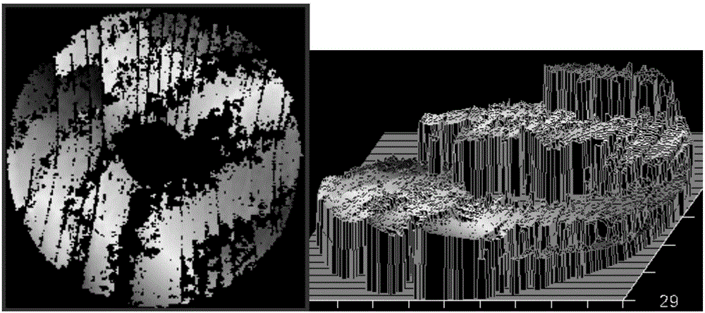
However, for aspheric surfaces with large aperture and large offset, especially in the initial polishing stage, since the surface of the mirror does not reach a high reflectivity at this time, it cannot meet the detection requirements of CGH and other transmissive components, even if the reflectivity barely meets the detection requirements of CGH. , due to the low accuracy of the surface shape of the mirror at this stage, and the large deviation, the surface shape error in the local area has exceeded the resolution capability of the laser interferometer, resulting in the partial absence of interference fringes, and it is impossible to obtain a full-aperture surface shape information, such as figure 1 shown
At the same time, as the diameter of the mirror increases, the traditional three-coordinate measurement method can no longer meet the detection accuracy requirements of the polishing stage.

Method used


Image

  • Pentaprism scanning detection method for aspheric reflector
  • Pentaprism scanning detection method for aspheric reflector
  • Pentaprism scanning detection method for aspheric reflector

Examples


Embodiment Construction

[0023] The present invention will be described in detail below with reference to the drawings and embodiments.

[0024] Such as image 3 As shown, the present invention provides a pentaprism scanning detection method for aspheric mirrors, which includes the following steps:

[0025] Step 1. Provision of equipment required for testing;

[0026] The equipment required for detection includes a laser transmitter, a reference pentaprism, a scanning pentaprism, a guide rail, a photodetector, and a sliding block movably connected to the guide rail; the reference pentaprism and the scanning pentaprism are both conventional pentaprisms.

[0027] Fix the photodetector device at the center of curvature of the aspheric mirror, install the guide rail in the direction perpendicular to the optical axis of the aspheric mirror, and install the laser transmitter, reference pentaprism and scanning pentaprism on the guide rail in turn, refer to the pentaprism The scanning pentaprism is fixedly installed...


PUM


Abstract

The present invention discloses a pentaprism scanning detection method for an aspheric reflector. The method comprises: 1) arranging a device required for detection; 2) performing scanning detection of a single bus; 3) performing scanning detection of the next bus of the rotation angle a of the aspheric reflector after the scanning of the single bus is completed; and 4) performing detection data processing and fitting. All the angle differences are transited to the slope values of the corresponding positions of the reflective surface of the aspheric reflector, the slope values are fitted with the Zernike gradient polynomial, and the low-order surface-shaped error parameters of the aspheric reflector are obtained. The high-precision low-order surface-shaped error parameters of the aspheric reflector can be obtained.

Description

Technical field [0001] The invention belongs to the technical field of optical system detection, and in particular relates to a pentaprism scanning detection method for aspheric mirror detection. Background technique [0002] The use of aspherical optical elements in the optical system can not only reduce the size and weight of the optical system, reduce the complexity of the system, but also correct aberrations and improve image quality, thereby greatly improving system performance. Therefore, aspheric optical components are the core components of military and civilian high-performance optical systems. They are used in aviation and aerospace remote sensing, astronomical observation, deep space exploration and photoelectric tracking instruments, lithography objective lenses, high-performance camera (camera) lenses and many other There are a wide range of applications in the field of optoelectronic instruments. [0003] However, with the continuous development of space optics techn...

Claims


Application Information

Patent Timeline
Patent Type & Authority Applications(China)
IPC IPC(8): G01B11/24
CPCG01B11/24
Inventor 张学军戚二辉薛栋林罗霄范镝
Owner CHANGCHUN INST OF OPTICS FINE MECHANICS & PHYSICS CHINESE ACAD OF SCI
Learn More