Manufacturing method for large thin-walled impeller

A manufacturing method and impeller technology, which is applied in the field of impeller manufacturing, can solve the problems of flow cooling medium damage, low structure and performance, and reduce machining accuracy, and achieve the effects of improving exhaust and cooling, high surface roughness, and improving surface accuracy

Active Publication Date: 2016-12-21
HIMILE MECHANICAL SCI & TECH (SHANDONG) CO LTD
View PDF5 Cites 8 Cited by
  • Summary
  • Abstract
  • Description
  • Claims
  • Application Information

AI Technical Summary

Problems solved by technology

[0004] 1) When low-pressure casting large thin-walled impellers, the pressure control of the entire casting process cannot be controlled in the same way as ordinary impeller low-pressure casting. Large-scale thin-walled impellers require more precise pressure control during the casting process, and the process of pressure control is also difficult. It should be more in line with the characteristics of large thin-walled impellers;
[0005] 2) When using existing casting molds for casting of large thin-walled impellers, often due to the unreasonable mold structure, the cooling sequence of the upper and lower molds is not from top to bottom, and the impeller castings are cooled from the outside to the inside , the internal blade structure of the impeller cannot get an effective cooling effect, the cooling speed of the impeller casting is not uniform throughout the cooling process, the cooling degree is not uniform, and the final formed impeller casting has defects such as shrinkage and porosity;
[0006] 3) Due to the large diameter of the large thin-walled impeller, the existing casting mold has poor air permeability when casting a large impeller, resulting in poor exhaust during the casting process, and resistance will be generated when the casting solution is filled into the mold, resulting in Insufficient pouring of impeller castings, or the gas in the mold cannot be discharged, and molten metal gas entrainment occurs, which causes defects such as pores and sand holes in the impeller castings, and the structure and performance are low, which affects the performance of the impeller castings;
[0007] 4) Since the impeller wall is relatively thin, especially for large thin-walled closed impellers, the thinnest part is less than 1.2mm, direct clamping is easy to cause deformation and rupture, causing damage to the impeller, which will not only further bring troubles for subsequent lathe processing Difficulty, and in most cases, after the impeller is damaged, the impeller will be scrapped, which greatly increases the production cost;
[0008] 5) Due to the complexity of the clamping tools, many surfaces on the impeller have not been machined, which greatly reduces the preci...

Method used


Image

  • Manufacturing method for large thin-walled impeller
  • Manufacturing method for large thin-walled impeller
  • Manufacturing method for large thin-walled impeller

Examples


Embodiment 1

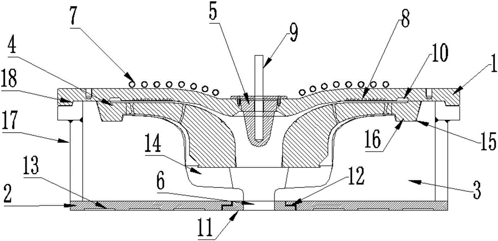
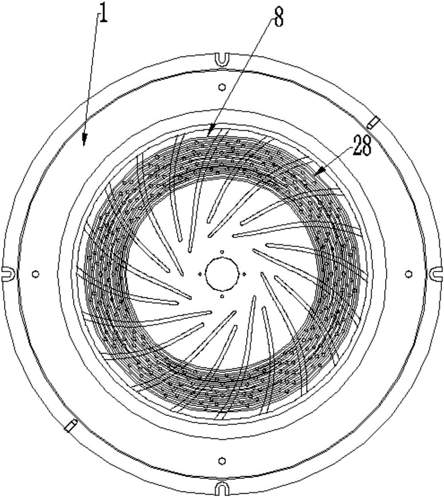
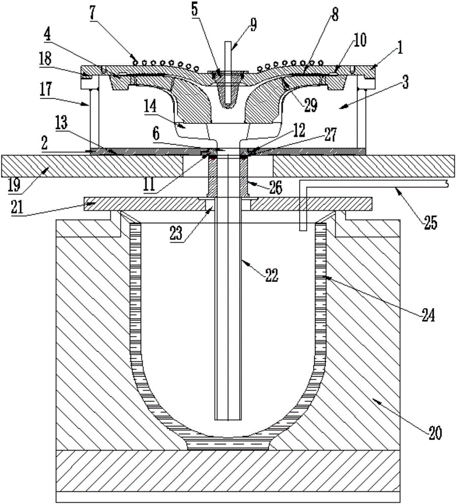
[0080] Such as figure 1 As shown, the casting mold includes an upper mold 1 and a lower mold 2 correspondingly arranged up and down, and a sand mold 3 and a core 4 are arranged in the cavity formed by the upper mold 1 and the lower mold 2, and the upper mold 1 and the lower mold 2 select metal Mold, core 4 selects gypsum core; Upper mold 1 is provided with cooling cone 5 for cooling the inside of the impeller, lower mold 2 is provided with gate 6 for casting solution to enter, and the top of upper mold 1 is provided with for cooling The upper mold 1 is provided with a plurality of cooling rings 7 for jet cooling, and the lower surface of the upper mold 1 is provided with a plurality of ring grooves 8 for exhausting the gas generated during the casting process. The combination of the core 4 and the sand mold 3 in the mold is beneficial to the heat preservation of the bottom aluminum liquid and the feeding of the casting; the cooling ring 7 and the cooling cone set on the upper...

Embodiment 2

[0121] The fixture in the heat treatment in this embodiment includes a heat-resistant supporting plate for placing the impeller, and a blade fixing protection device for protecting the upper and lower blades is provided on the upper surface of the heat-resistant supporting plate. The center of the protection device has a cooling medium flow channel opening; the upper and lower blades are protected by the blade fixing protection device to effectively prevent the deformation of the blades.

[0122] The vane fixing protection device includes an upper vane cover plate arranged above the flow channel opening, and a lower vane cover plate located below the flow channel opening. The upper vane cover plate and the lower vane cover plate are respectively arranged horizontally. A plurality of connecting pieces are arranged vertically, leaving a cooling medium inlet.

Embodiment 3

[0124] The fixture in the turning process in this embodiment includes a bottom plate, and the working surface of the bottom plate is provided with a concave part, and the concave part is matched with the working surface where the large circular surface of the impeller end is located, and the edge of the concave part is provided for locking the first circular surface of the impeller end to the bottom plate The first pressing part is detachably provided on the working surface of the bottom plate for locking the second round surface of the impeller end to the bottom plate. The second pressing part is provided with the second pressing part.

[0125] This solution omits the second recess in the first solution, which can also satisfy the rapid positioning of the impeller. At this time, the fastening plate in the second pressing part is preferably fastened by the bolts arranged in a triangle, so as to improve stability sex.


PUM

PropertyMeasurementUnit
Surface roughnessaaaaaaaaaa

Abstract

The invention discloses a manufacturing method for a large thin-walled impeller. An upper mold body of a mold is internally provided with annular grooves and exhaust plugs so that exhausting can be improved, a cooling cone is arranged on the upper mold body and cooling rings are arranged on the upper surface of the upper mold body so that the cooling speed of castings can be increased, and meanwhile a sand mold is used at the bottom of a gypsum core so that heat preservation of molten aluminum at the bottom and feeding of the castings can be facilitated. The program allowing integral casting of the thin-walled and large-size impeller to be achieved by improving exhausting and cooling is adopted for the mold, the forming quality is good, and precision is high; a first concave part is arranged to position the first circular face of the end portion of the impeller, the impeller is locked to a bottom plate through first pressing pieces, welding is not needed, and fixation is convenient and rapid; and after the first round of machining is conducted on the impeller, a second concave part is arranged to position the second circular face of the impeller, fastening is conducted through second pressing pieces, machining is conducted on the impeller in order, the situation that some faces are not machined due to clamps or other reasons is avoided, and the surface precision of the impeller is improved.

Description

technical field [0001] The invention relates to the field of impeller manufacturing, in particular to a method for manufacturing a large thin-walled impeller. Background technique [0002] The impeller is an important part of products such as water turbines, steam turbines, aero engines, rocket engines, expanders, pumps, fans, compressors, etc. Its function is to pressurize or convert the gas or liquid passing through it. The impeller is usually composed of discs, blades, connectors and other parts, and is divided into open, semi-closed and closed impellers according to their structure. [0003] Most closed integral impellers have thin walls, twisted blades, complex structures, high requirements for dimensional accuracy and surface roughness, and cannot be manufactured by machining. In order to obtain impellers with high precision and high surface roughness, precision casting processes are required. Due to precision casting production The process is complex and technically ...

Claims


Application Information

Patent Timeline
IPC IPC(8): B22D18/04
CPCB22D18/04
Inventor 张伟韩桂强张增超范纪成刘杰张恭运杜平
Owner HIMILE MECHANICAL SCI & TECH (SHANDONG) CO LTD
Why Eureka
Try Eureka