Jet lubrication structure

A spray-type, structural technology, applied in the direction of pressure lubricant, engine lubrication, machine/engine, etc., can solve the problems of high frictional resistance between the piston and the cylinder hole, the heat cannot be dissipated in time, and the top of the piston is burned to achieve lubrication. Good effect, improve power output or transmission efficiency, and reduce friction loss

Active Publication Date: 2019-07-26
LONCIN MOTOR
View PDF7 Cites 0 Cited by
  • Summary
  • Abstract
  • Description
  • Claims
  • Application Information

AI Technical Summary

Problems solved by technology

[0004] In a traditional engine oil lubrication system, it includes an oil pump, an oil filter and a lubricating oil passage placed on the crankcase. The oil pump is equipped with a gear transmission, and the oil stored at the bottom of the crankcase is sucked into the main oil passage and sent to the oil passage that needs to be lubricated. At the parts of the main oil passage, crankshaft journals, balance journals, etc. are usually required to be lubricated, and the interior of the piston cavity is usually lubricated by splashed oil, but due to factors such as angle and space, the splash into the piston cavity There is not much oil inside, and the lubrication effect is not good, so that the friction resistance between the piston and the cylinder hole is relatively large, and the friction surface is severely worn; at the same time, the high temperature generated by the engine combustion is transmitted to the piston, causing the temperature of the piston to be very high, and the friction between the piston and the cylinder liner generates heat. If it cannot be dispersed in time, it will easily cause abnormal phenomena such as piston deformation and thermal expansion, piston ring burning and piston top damage.

Method used


Image

  • Jet lubrication structure
  • Jet lubrication structure
  • Jet lubrication structure

Examples


Embodiment Construction

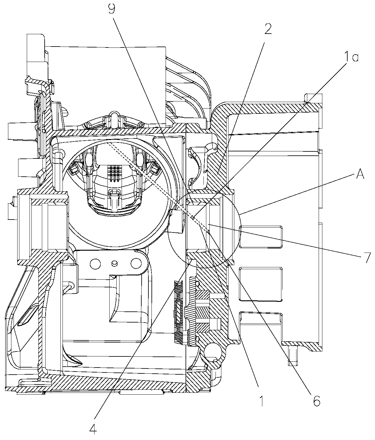
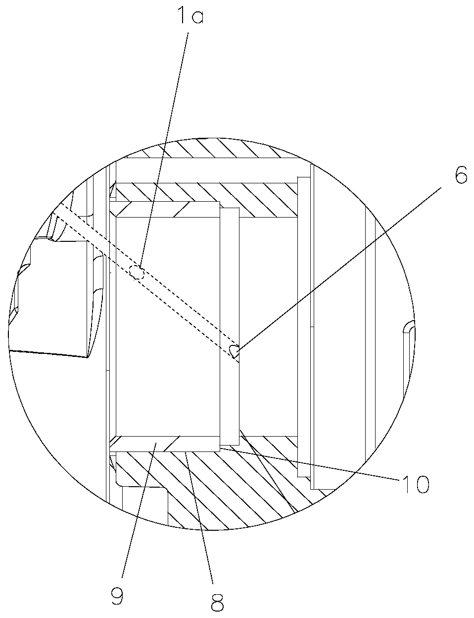
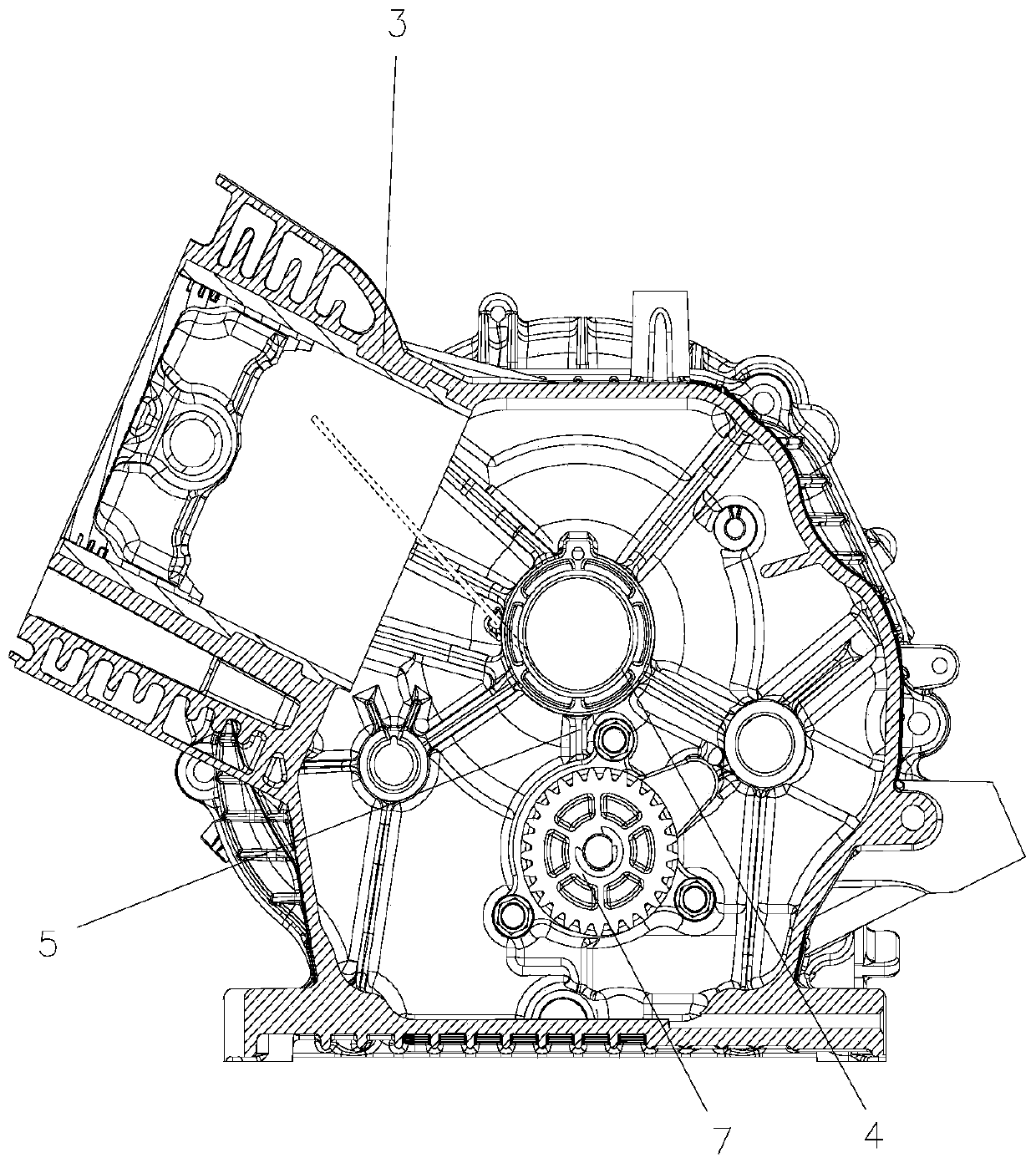
[0022] figure 1 It is a structural schematic diagram of the present invention, figure 2 for figure 1 Enlarged view of A in the middle, image 3 It is another schematic diagram of the structure of the present invention, as shown in the figure, the injection lubrication structure in this embodiment includes an injection oil channel 1 arranged in the box, the injection oil channel 1 has an oil injection port 1a, and the injection oil channel 1 The oil injection direction of the oil port 1a is facing the piston cavity of the box body; the box body includes the crankcase and the cylinder 3 fixed to the crankcase, as shown in the figure, the crankcase includes the crankcase body and the crankcase cover 2, this Embodiment The injection oil passage 1 is arranged on the crankcase cover 2 of the crankcase. Of course, there is injection machine oil with a certain pressure in the injection oil passage 1. At the same time, the oil injection direction of the oil injection port 1a is faci...


PUM


Abstract

The invention discloses an injection type lubricating structure. The structure comprises an injection oil way arranged in a box body, the injection oil way is provided with an oil injection opening, the oil injection direction of the oil injection opening right faces a piston cavity of the box body, engine oil injected out of the oil injection opening can reach the top face of the piston cavity, the top of the piston cavity can be effectively cooled, motion components in a cylinder body are effectively lubricated, normal running of a steam cylinder is ensured, excessive losses of the power of an engine are avoided, the structure is simple, and machining is convenient; meanwhile, a shaft neck which rotates at a high speed enables the engine oil injection strength to be larger, the sputtering and lubricating range of surrounding components is widened and the sputtering and lubricating strength of the surrounding components is improved while it is ensured that the cooling flow is sufficient, meanwhile, the injection engine oil flowing out at a high speed is beneficial to inner circle oil distribution of a shaft neck supporting base, and it is ensured that the lubricating effect is good.

Description

technical field [0001] The invention relates to the field of engine lubrication, in particular to a jet lubricating structure. Background technique [0002] A general-purpose engine usually has moving parts such as a crankcase, a crankshaft, a piston, and a connecting rod. The crankcase is one of the main components of a gasoline engine, and the crankcase is composed of the crankcase cover and the crankcase body. [0003] The engine crankcase stores engine oil. During the working process of the engine, the working surface of the moving parts is uneven. In order to prevent dry friction between the metal parts, the general engine needs to be equipped with a lubrication system to form an oil film between the friction surfaces. Realize liquid friction, thereby reducing frictional resistance, reducing power consumption, and improving the reliability and durability of engine work. [0004] In a traditional engine oil lubrication system, it includes an oil pump, an oil filter and ...

Claims


Application Information

Patent Timeline
Patent Type & Authority Patents(China)
IPC IPC(8): F01M1/08F01M1/06
CPCF01M1/06F01M1/08F01M2001/062F01M2001/083
Inventor 刘兵曾勇戴瑞义谭宗发李仁石秦金菊王昌勇刘林
Owner LONCIN MOTOR
Why Eureka
Try Eureka