A Plasma Synthetic Jet Generator with Controllable Cavity Temperature and Its Application

A plasma and synthetic jet technology, applied in the direction of plasma, electrical components, etc., can solve the problems of improving performance, low jet velocity, and reduced jet flow, so as to improve continuous service life, increase jet intensity, and increase discharge energy. Effect

Active Publication Date: 2021-02-09
CHINA ACAD OF AEROSPACE AERODYNAMICS
View PDF7 Cites 0 Cited by
  • Summary
  • Abstract
  • Description
  • Claims
  • Application Information

AI Technical Summary

Problems solved by technology

Vortex generators are generally arranged on the surface of wings or flaps to generate flow direction vortices, enhance the mixing of main flow and boundary layer flow, and achieve the purpose of inhibiting separation, but they cannot improve performance under different flight conditions; blowing air suction system Energy can be injected into the boundary layer through an external air source, but its size and power consumption are too large; the high-frequency jet energy generated by diaphragm and piezoelectric synthetic jet generators, etc., is small, and the jet velocity is small, even if it has been aimed at The effect is amplified permanently through various mechanisms, but the effect is still not enough to meet the practical standard, so it is rarely used in high-speed flow; the piston-type synthetic jet generator can obtain higher energy output, but is limited by Limited to the structural form, its jet frequency cannot reach a high level
[0004] The plasma synthetic jet generator heats the gas in the confined cavity instantaneously through the DC high-voltage pulse discharge, forcing the airflow to eject, and at the same time obtains a higher jet velocity and jet frequency. However, due to the high temperature in the cavity, the cavity inside the cavity Density is reduced and therefore jet flow is reduced

Method used


Image

  • A Plasma Synthetic Jet Generator with Controllable Cavity Temperature and Its Application

Examples


Embodiment Construction

[0025] The present invention will be described in detail below in conjunction with the accompanying drawings and examples.

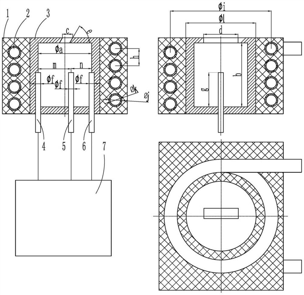
[0026] figure 1 It is a schematic structural diagram of a plasma synthetic jet generator with controllable cavity temperature provided by an embodiment of the present invention. Such as figure 1 As shown, the plasma synthetic jet generator with controllable chamber temperature includes: thermal management components and plasma synthetic jet generator; electrodes include anode 4, cathode 6 and excitation pole (also known as trigger pole) 5; the chamber Body 3, the electrode and the DC high-voltage pulse power supply 7 constitute a plasma synthetic jet generator; the heat management component includes the heat-conducting support structure 1 and heat pipe 2; the DC high-voltage pulse power supply and the electrode pass through a wire Connected; the electrodes form a high-frequency arc under the excitation of the DC high-voltage pulse power supply (voltage...


PUM


Abstract

A plasma synthetic jet generator with controllable cavity temperature and its application. The nozzle includes: a heat conduction support structure, a heat pipe, a cavity, electrodes and a DC high-voltage pulse power supply; wherein the electrodes include an anode, a cathode and an excitation electrode; The cavity, the electrode and the DC high-voltage pulse power supply constitute a plasma synthetic jet generator; the heat management component includes the heat-conducting support structure and heat pipes; the DC high-voltage pulse power supply and the electrode are connected through wires ; The electrode forms a high-frequency arc under the excitation of the DC high-voltage pulse power supply. In one excitation cycle, the arc heats the gas in the cavity, and sprays it into the main flow through the oblique hole in the cavity, and the high-temperature gas is ejected Afterwards, the density in the cavity decreases and the temperature rises, and the mainstream gas is sucked into the cavity through the oblique hole of the cavity to form a working cycle; the heat management component conducts the high temperature of the cavity to the cold end of the heat pipe, which can The temperature in the cavity is lowered, thereby increasing the density in the cavity. The invention greatly improves the momentum of jet flow ejected from the plasma synthetic jet flow generator.

Description

technical field [0001] The invention belongs to the field of aerodynamic active flow control, in particular to a plasma synthetic jet flow generator with controllable cavity temperature. Background technique [0002] When the aircraft maneuvers at a high angle of attack, it is often accompanied by the flow separation of the wing surface. The separation makes the air flow no longer attached to the wing surface, resulting in an unstable vortex. When the stall angle of attack is reached, the lift drops sharply, which may cause control reversal and cause serious flight accidents. The flow control technology of airfoil fluid separation can effectively reduce the flow separation, and it is one of the key technologies for aircraft to fly at high angle of attack. [0003] At present, the flow control forms for controlling separation mainly include vortex generators, air blowing systems, diaphragm synthetic jet generators, piezoelectric synthetic jet generators, and piston synthetic...

Claims


Application Information

Patent Timeline
Patent Type & Authority Patents(China)
IPC IPC(8): H05H1/28
CPCH05H1/28
Inventor 魏巍杨辉赵永胜
Owner CHINA ACAD OF AEROSPACE AERODYNAMICS
Why Eureka
Try Eureka