One-piece molded inductor and manufacturing method thereof
A manufacturing method and inductor technology, which is applied in the manufacture of inductors/transformers/magnets, transformer/inductor cores, circuits, etc., can solve problems such as component gaps, improve current resistance performance, reduce production costs, and reduce magnetic losses. Effect
- Summary
- Abstract
- Description
- Claims
- Application Information
AI Technical Summary
Problems solved by technology
Method used
Image
Examples
Embodiment 1
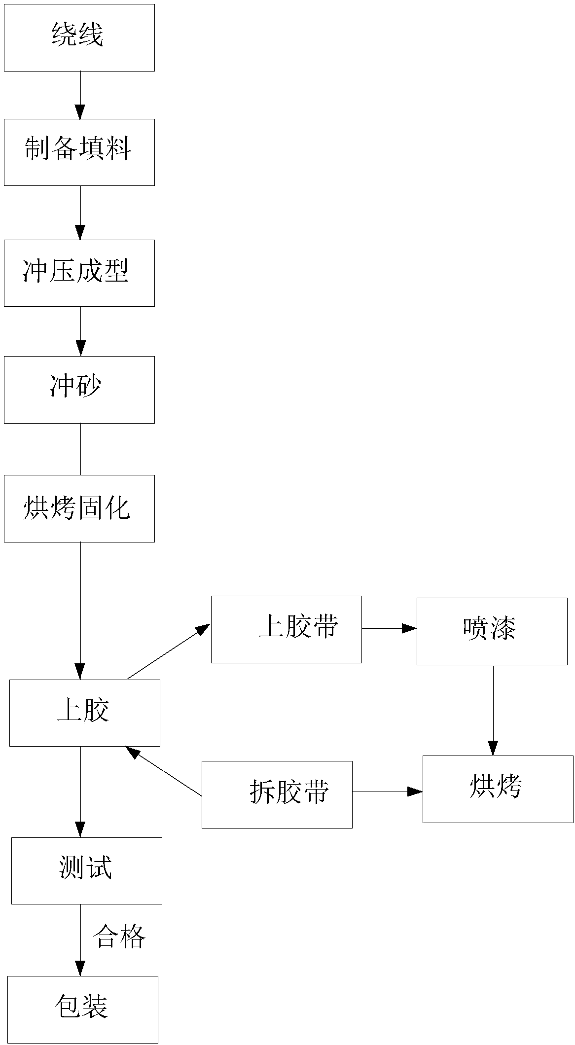
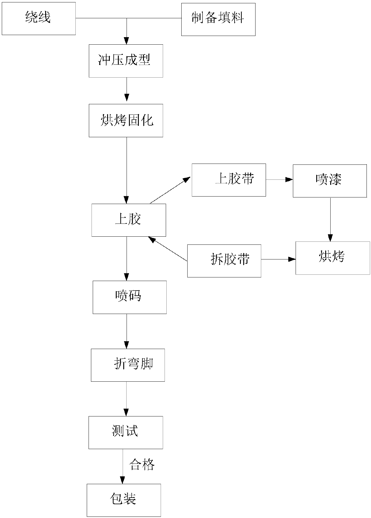
[0040] The copper wire is wound into a coil, the two ends of which are respectively electrically connected to the first electrode pin and the second electrode pin; the reduced iron powder and the liquid silica gel are mixed uniformly according to the weight ratio of 100:2 to form a filler, and the filler is heated at a temperature of 70 Keep the temperature for 0.5h at ℃; place the coil connected with the first electrode leg and the second electrode leg in a mold, where a marking area is provided inside the mold, and the filler is injected into the mold to form an integral inductor by stamping. Wherein, the filler forms a magnetic core in the middle of the coil, and an outer magnet is formed on the outside of the coil, and the magnetic core and the outer magnet are integrally formed to wrap the coil. Wash the surface of the above-mentioned integrated inductor with glass sand for 15s, then place the washed integrated inductor at 78℃ for 0.5h; then at 140℃ for 0.6h; finally at 160...
Embodiment 2
[0042] The copper wire is wound into a coil, the two ends of which are respectively electrically connected to the first electrode pin and the second electrode pin; the carbon-based iron powder, liquid silica gel and γ-aminopropylmethyldimethoxysilane are mixed uniformly to obtain the filler , Wherein the weight ratio of carbon-based iron powder to liquid silica gel is 100:10, and the weight ratio of γ-aminopropylmethyldimethoxysilane filler to liquid silica gel is 1:99; the filler is placed at a temperature of 80℃ The lower heat preservation is 0.3h; the coil connected with the first electrode leg and the second electrode leg is placed in the mold, where a marking area is provided inside the mold, and the filler is injected into the mold to form an integral inductor by stamping, wherein, The filler forms a magnetic core in the middle of the coil, and an outer magnet is formed on the outside of the coil, and the magnetic core and the outer magnet are integrally formed to wrap the...
Embodiment 3
[0044] The copper wire is wound into a coil, the two ends of which are respectively electrically connected to the first electrode pin and the second electrode pin; the iron-based amorphous alloy and the liquid silica gel are mixed uniformly according to the weight ratio of 100:3 to form a filler, and the filler is heated Keep the temperature at 76°C for 1 hour; place the coil connected with the first electrode leg and the second electrode leg in the mold, inject the filler into the mold, and press to form an integral inductor. The filler forms a magnetic field in the middle of the coil. A core, an outer magnet is formed on the outside of the coil, and the magnetic core and the outer magnet are integrally formed to wrap the coil. Then place the integrated inductor at 80°C for 0.5h; then bake at 137°C for 0.52h; finally, bake at 164°C for 1h, so that the integrated inductor is completely cured; then the cured integrated inductor The first electrode leg and the second electrode le...
PUM
| Property | Measurement | Unit |
|---|---|---|
| thickness | aaaaa | aaaaa |
| thickness | aaaaa | aaaaa |
Abstract
Description
Claims
Application Information
 - R&D
- Intellectual Property
- Life Sciences
- Materials
- Tech Scout
- Unparalleled Data Quality
- Higher Quality Content
- 60% Fewer Hallucinations
Browse by: Latest US Patents, China's latest patents, Technical Efficacy Thesaurus, Application Domain, Technology Topic, Popular Technical Reports.
© 2025 PatSnap. All rights reserved.Legal|Privacy policy|Modern Slavery Act Transparency Statement|Sitemap|About US| Contact US: help@patsnap.com


