Gantry moving beam type vertical turning-milling combined machining center

A composite machining center and vertical lathe technology, applied in the direction of manufacturing tools and other manufacturing equipment/tools, can solve the problem that the processing capacity of embedded chips cannot support advanced network applications, and achieve high cost performance, good dynamic performance, and processing The effect of strong stability

Inactive Publication Date: 2017-01-04
SHENYANG MASCH TOOL CO LTD
View PDF6 Cites 3 Cited by
  • Summary
  • Abstract
  • Description
  • Claims
  • Application Information

AI Technical Summary

Problems solved by technology

Other traditional systems can also achieve networking, but need to add a network card module. Due to the framework, the content and speed of data transmitted through the network will be limited, and the limited processing capacity of embedded chips cannot support advanced network applications.

Method used


Image

  • Gantry moving beam type vertical turning-milling combined machining center
  • Gantry moving beam type vertical turning-milling combined machining center
  • Gantry moving beam type vertical turning-milling combined machining center

Examples


Embodiment Construction

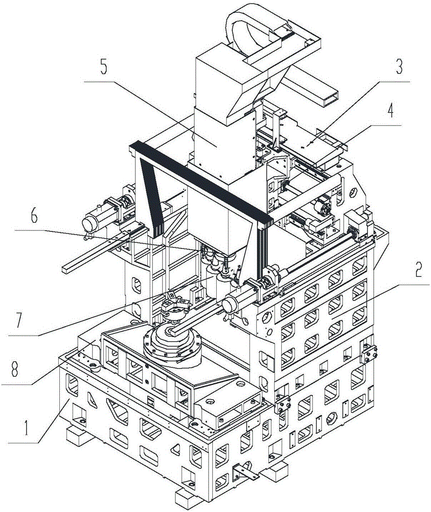
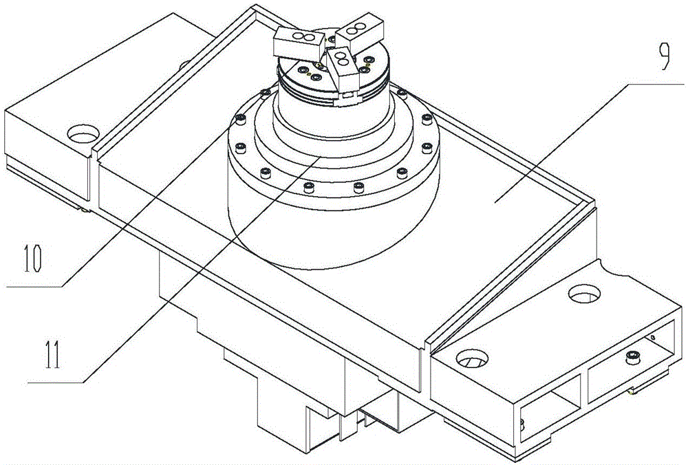
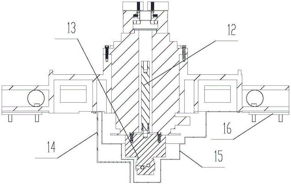
[0024] A gantry moving beam type vertical turning and milling compound machining center of the present invention, the structure and implementation scheme are as follows Figure 1-2-a , 2-b, including the setting of the gantry moving beam machine tool, which is characterized in that: i5CNC, the underlying motion control system based on the Internet, adopts the EtherCAT bus protocol to control PLC and motor drive. Carry out communication, accept instructions or send machine tool information; structural modularization: the vertical turning spindle unit 8 is fixed on the front horizontal surface of the gantry moving beam frame bed 1; the gantry moving beam frame setting includes the bed 1, left and right columns 2 is fixed on the bed 1, the crossbeam 3 is fixed on the guide rail slider and moves forward and backward on the column 2 in the Y axis, the sliding saddle 4 connected with the headstock 5 is fixed on the guide rail slider and moves on the crossbeam 3 in the X axis left and...


PUM


Abstract

The invention provides a gantry moving beam type vertical turning-milling combined machining center. The gantry moving beam type vertical turning-milling combined machining center is characterized in that a bottom movement control system i5CNC based on the Internet condition is in communication with other terminals directly through the Internet, and an EtherCAT bus protocol is used for controlling a PLC and motor driving; a vertical turning spindle unit is fixed to the horizontal plane of the front side of a gantry moving beam type frame lathe bed; a vertical turning spindle is vertically fixed in a vertical turning supporting base, a central solid chuck is coaxially fixed to the vertical turning spindle, a locking oil cylinder and a pull rod are fixed to the lower end of the vertical turning spindle, and the locking oil cylinder is controlled to drive the pull rod and the central solid chuck to achieve clamping or loosening; and dual drive is adopted for the Y axis, a spindle power unit is reversely arranged in a spindle box, a bamboo hat type tool changer is fixed to the rear side of the lathe bed, and the tool taking function of the spindle is achieved through the X axis, the Y axis and the Z axis. The gantry moving beam type vertical turning-milling combined machining center has the beneficial effects that one axis is added, both the milling function and the turning function can be integrally achieved in the spindle unit, and high-speed rotating and positioning can be achieved; and a turning tool sliding plate assembly of the spindle unit is omitted, so that the cost is reduced, and the cost performance is high. The gantry moving beam type vertical turning-milling combined machining center has better high-and-low speed properties and dynamic performance.

Description

technical field [0001] The invention belongs to the field of metal cutting machine tool manufacturing, and in particular relates to a turning-milling compound machining center with a vertical turning spindle unit on a gantry moving beam frame. Background technique [0002] At present, the existing CNC vertical turning-milling compound machine tool adopts the beam fixing method and only has X and Z axes, which is inconvenient for processing and adjustment. Moreover, the movement direction of the X-axis includes two parts, the spindle assembly and the turning tool slide plate assembly, to realize the combined function of turning and milling, and the cost is high. [0003] Computerized numerical control (CNC for short) system is a system that uses computers to control processing functions and realize digital control. The CNC system performs part or all of the digital control functions according to the control program stored in the computer memory, and is equipped with an inter...

Claims


Application Information

Patent Timeline
IPC IPC(8): B23P23/02
CPCB23P23/02
Inventor 关锡友董彦宏于春明薛佟赵星张中张传思李士博张童艾明旺徐龙
Owner SHENYANG MASCH TOOL CO LTD
Why Eureka
Try Eureka