
Multi-material composite 3D printer and working method and application of multi-material composite 3D printer

A 3D printer and working method technology, applied in the field of additive manufacturing, can solve the problems of low printing resolution, low mixing efficiency, and difficulty in printing a variety of materials, achieve a wide range of printing materials, solve the problem of low circuit resolution, printing droplets small diameter effect

Active Publication Date: 2017-01-04
QINGDAO TECHNOLOGICAL UNIVERSITY
View PDF5 Cites 25 Cited by
  • Summary
  • Abstract
  • Description
  • Claims
  • Application Information

AI Technical Summary

Problems solved by technology

[0003] 3D printing technology is also revolutionizing the production of lightweight structures, wearable devices and flexible electronic components, but existing 3D printing technology is still difficult to print complex structures where multiple materials are fused together
[0004] However, most of the existing 3D printing can only achieve single-material printing, and it is difficult to achieve macro / micro cross-scale manufacturing
Developed multi-material 3D printers such as Stratasys Objet500Connex33D and J750 printers, Voxel8's multi-material 3D electronic printer, 3D Systems' multi-material composite 3D printer PROJET 5500X, etc., have the following shortcomings: First, the printing resolution is still low At present, it is difficult to realize the printing of micro-scale structures, especially the macro / micro / nano multi-scale and cross-scale manufacturing; the second is that the multi-material mixing basically adopts the passive mixing method of materials, and the mixing efficiency is low and uneven
Therefore, the existing 3D printing has the following deficiencies and limitations in terms of multi-material and multi-scale printing: (1) The printing resolution is low, making it difficult to print micro-scale structures, especially macro / micro / nano multi-scale and cross-scale Scale manufacturing; (2) Active mixing of multi-materials cannot be realized; (3) Precise control of components of multi-materials cannot be realized; (4) Seamless transition between multi-materials cannot be realized (such as seamless transition from soft materials to hard materials) (5) Difficult to achieve micro-scale printing of high-viscosity materials; (6) Difficult to achieve simultaneous printing of more than three materials, especially organic integration with conductive materials; (7) Difficult to achieve integrated printing of structural materials and functional materials; ( 8) Multi-material and multi-scale integrated manufacturing of complex structures cannot be realized at present

Method used


Image

  • Multi-material composite 3D printer and working method and application of multi-material composite 3D printer
  • Multi-material composite 3D printer and working method and application of multi-material composite 3D printer
  • Multi-material composite 3D printer and working method and application of multi-material composite 3D printer

Examples


Embodiment 1

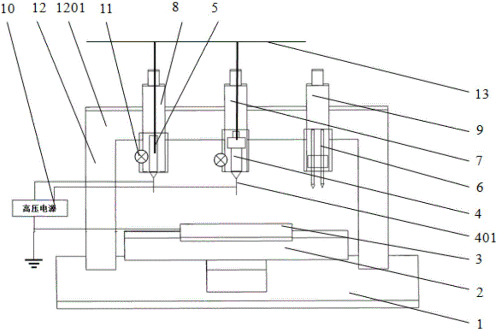
[0055] Such as figure 1 As shown, the multi-material composite 3D printer includes: base 1, x-y workbench 2, print bed 3, first nozzle 4, second nozzle 5, third nozzle 6, z-direction worktable 1 7, z-direction workbench II 8, z direction workbench III 9, high voltage power supply 10, UV curing light source 11, frame 12, pressure pipeline 13. The base 1 is placed at the bottom; the x-y workbench 2 is placed on the base 1; the print bed 3 is fixed on the x-y workbench 2; the first nozzle 4 is placed directly above the print bed 3, and is aligned with the z-direction workbench I 7 The z-direction workbench I 7 is fixed on the beam 1201 of the frame 12; the second spray head 5 is placed above the printing bed 3 and connected with the z-direction workbench II 8; the z-direction workbench II 8 is fixed on the machine on the beam 1201 of the frame 12; the third nozzle 6 is placed above the printing bed 3 and connected with the z-direction workbench III 9; the z-direction workbench I...

Embodiment 2

[0069] The working method of multi-material composite 3D printer comprises the following steps:

[0070] Step 1: Utilize the first shower head 4 and / or the third shower head 6 to print the base layer (bottom layer) and the structural layer;

[0071] Step 2: When it is necessary to print a circuit (functional layer), start the second nozzle 5 to print a specific circuit (functional layer) on the structural layer;

[0072] Step 3: If the object to be printed is a single-layer structure, go directly to step 4; if it is a multi-layer structure, repeat steps 1 and 2 until the last layer of circuit printing is printed;

[0073] Step 4: Print the topmost structure by using the first spray head 4 and / or the third spray head 6, and complete the printing of the final packaging structure.

[0074] When printing the circuit in step 3, the pause function can also be used to embed electronic components such as sensors, antennas, batteries, and LEDs.

[0075] For the second spray head 5, a...

Embodiment 3

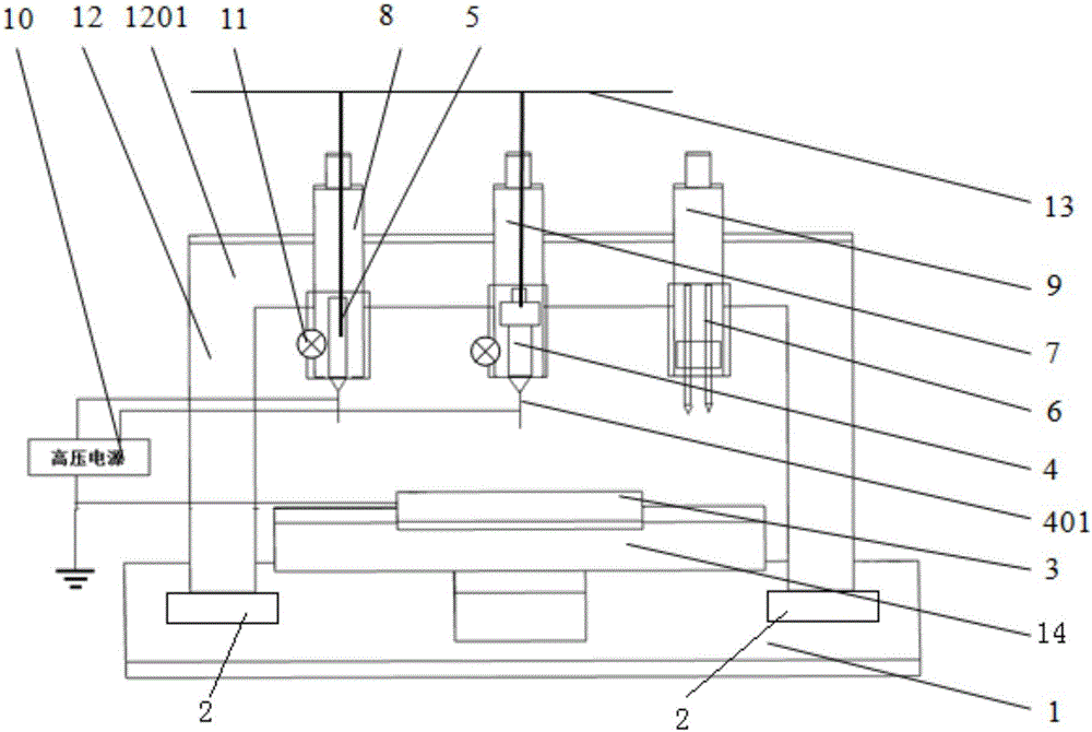
[0079] Such as image 3 As shown, the multi-material composite 3D printer includes: base 1, x-y workbench 2, print bed 3, first nozzle 4, second nozzle 5, third nozzle 6, z-direction worktable 1 7, z-direction workbench II 8, z direction workbench III 9, high voltage power supply 10, UV curing light source 11, frame 12, pressure pipeline 13, fixed workbench 14. The base 1 is placed at the bottom; the x-y table 2 is placed on the base 1; the printing bed 3 is fixed on the fixed table 14; the fixed table 14 is placed on the base 1; the first nozzle 4 is placed directly above the printing bed 3 , and connected with the z-direction workbench I 7; the z-direction worktable I 7 is fixed on the beam 1201 of the frame 12; the second nozzle 5 is placed above the printing bed 3 and connected with the z-direction workbench II 8; The z-direction workbench II 8 is fixed on the beam 1201 of the frame 12; the third nozzle 6 is placed above the printing bed 3 and connected with the z-directi...


PUM

PropertyMeasurementUnit
The inside diameter ofaaaaaaaaaa

Abstract

The invention discloses a multi-material composite 3D printer and a working method and application of the multi-material composite 3D printer. The multi-material composite 3D printer comprises a base which is provided with a working table and a rack, the working table is provided with a printing bed for supporting a printed object, the rack is at least fixedly provided with a first spray head, a second spray head and a third spray head, and the first spray head, the second spray head and the third spray head are all located above the printed object; the first spray head is a multi-material active mixing spray head, the second spray head comprises a micro injector material barrel and an electric conduction spray nozzle arranged at the lower portion of the micro injector material barrel, and the third spray head at least comprises two fusion deposition spray heads, wherein one fusion deposition spray head is used for printing structural materials, and the other fusion deposition spray head is used for printing supporting materials; and electric conduction spray nozzles of the first spray head and the second spray head are both connected with the positive pole of a power source, and the printing bed is connected with the negative pole of the power source. Multi-material and multi-scale complex structure integrated manufacturing is achieved, the structural materials and functional materials are integrally printed, and the technical bottleneck for limiting integrated manufacturing of materials, structures and devices is broken through.

Description

technical field [0001] The invention belongs to the technical field of additive manufacturing, and in particular relates to a multi-material composite 3D printer and its working method and application. Background technique [0002] New generation of electronic products (embedded electronics, flexible electronics, wearable devices, structural electronics), new materials (functionally graded materials, composite materials, metamaterials, smart materials), new energy, tissue engineering (tissue scaffolds, capillary ), Internet of Things RFID, soft robotics, MEMS, aerospace and other fields have huge demands for integrated manufacturing of multi-material, multi-scale complex structures. For example, 3D printing of embedded electronic products is a typical multi-material and multi-scale 3D printing. Printing materials include structural materials (plastics, polymers, ceramics, metals, etc.), conductive materials, dielectric materials (insulating materials), etc. The characterist...

Claims


Application Information

Patent Timeline
IPC IPC(8): B29C67/00B33Y30/00B33Y10/00
CPCB33Y10/00B33Y30/00
Inventor 兰红波李涤尘
Owner QINGDAO TECHNOLOGICAL UNIVERSITY
Learn More