Aeration control system based on oxygen uptake rate tester and method of aeration control system

A technology for oxygen consumption rate and control system, applied in chemical instruments and methods, water treatment parameter control, sustainable biological treatment, etc.

Inactive Publication Date: 2017-01-04
尚川(北京)水务有限公司
View PDF4 Cites 15 Cited by
  • Summary
  • Abstract
  • Description
  • Claims
  • Application Information

AI Technical Summary

Problems solved by technology

[0004] At present, the most common method of aeration control in China is still a relatively extensive manual debugging method. The aeration volume is usually determined according to the operator's experience. If the effluent water quality does not undergo long-term and obvious fluctuations, the aeration volume will not be adjusted Real-time adjustment; once the operating conditions change, the adjustment of the aeration volume is still only adjusted up and down according to experience, resulting in insufficient or over-aeration problems, and even the aeration system of some treatment plants is under normal load for a long time Running under the state, not only does not guarantee the quality of the effluent water, but also causes a lot of waste of energy consumption
Moreover, most of the control strategies do not involve the mass transfer efficiency of oxygen, and the relationship between the aeration rate and the conversion rate cannot be accurately grasped, resulting in inaccurate control of the aeration rate.
[0005] At present, for systems that use ORP (Oxidation-Reduction Potential) and pH for aeration control, since there is no direct linear relationship between ORP and pH and aeration volume, and the ORP value is seriously delayed in a short period of time, in the process of nitrification-denitrification It is difficult to determine accurately, so it is not widely used in practical applications
The basic principle of aeration control using water quality indicators as feed-forward is to calculate the amount of oxygen that needs to be provided through the concentration of pollutants. However, most of the sewage water quality indicators rely on experimental measurements, and the measurement time takes hours or even days. This has an impact on real-time control. not big
Online water quality testing instruments also have a delay of several hours, are expensive, and have not yet been fully popularized
[0006] The intermittent aeration makes the aerobic pond alternate between aeration and non-aeration by repeatedly starting and stopping the blower, which is simple and practical, but the control performance is unstable. The life of the fan, and the control of the aeration volume with a large difference will also reduce the accuracy of the aeration

Method used


Image

  • Aeration control system based on oxygen uptake rate tester and method of aeration control system
  • Aeration control system based on oxygen uptake rate tester and method of aeration control system
  • Aeration control system based on oxygen uptake rate tester and method of aeration control system

Examples


Embodiment 1

[0088] Set the desired dissolved oxygen concentration. The set dissolved oxygen value is to make the actual aeration amount as close or consistent as possible to the expected value by changing the aeration amount;

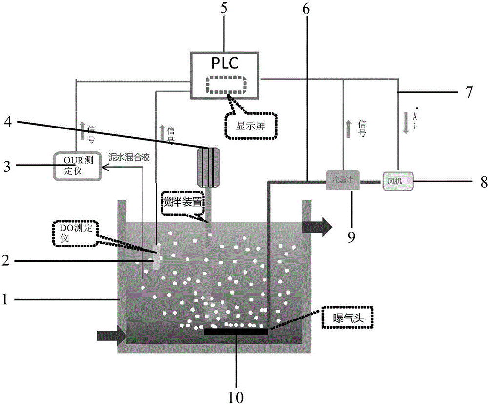
[0089] First write the control algorithm program in the above specification into the PLC control unit 5, when the aeration control system starts to operate, the dissolved oxygen (DO) measuring instrument 2 measures the DO concentration in the sewage in real time, and sends it to the PLC control unit through the data signal transmission line 7 5. The OUR measuring instrument 3 will feed back the data to the PLC control unit 5, and the flow meter 9 will transmit the air volume signal to the PLC control unit 5 in real time through the data signal transmission line 7, and the PLC control unit will calculate the required aeration volume through algorithm integration, and calculate The result is transmitted to the control blower 8 in the form of a signal, and the air volu...

Embodiment 2

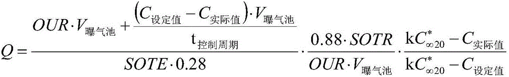
[0094] The volume of the aeration tank is 0.25m 3 , Since the measurement period of the OUR measuring instrument is 15 minutes, the control period is set to 15min, SOTE=20%, SOTR=0.03kg / h, k=0.75, C * ∞20 is the saturated dissolved oxygen value at 20°C;

[0095] The initial setting value of dissolved oxygen is 2. The aeration control can be started after connecting the OUR tester, DO tester and aeration system to the PLC. The OUR tester measures a value every 15 minutes, and the DO tester measures in real time , Each change of the three values ​​of OUR, OTE and DO will be transmitted to the PLC control cabinet through the signal transmission line, and the actual required air volume will be calculated, and the output signal will be sent to the fan to regulate the air volume of the fan. The value of the flowmeter will be displayed through the signal line and recorded on the PLC display.

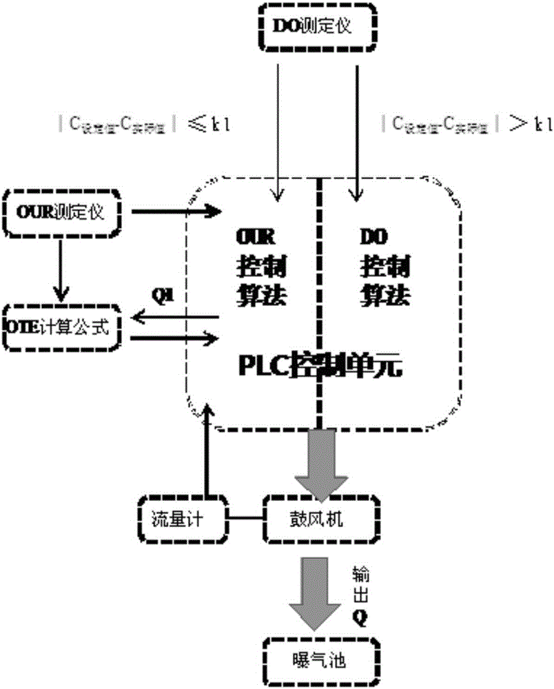
[0096] Under stable conditions, the OUR and OTE values ​​do not change much, and the con...


PUM


Abstract

The invention discloses an aeration control system based on an oxygen uptake rate tester. The aeration control system comprises a data collection unit, a PLC control unit and an aeration unit, wherein the data collection unit comprises an OUR tester and a DO tester; the aeration unit comprises an air blower, a micro-hole aeration head and a flow meter; and the PLC control unit comprises hardware including a control cabinet, a display screen and the like as well as control software, the control software comprises a control unit and a DO feedback protecting unit, and the control unit is mainly based on an OUR value, an OTE value and a dissolved oxygen value. The invention further provides a method for carrying out aeration control by virtue of the aeration control system. According to the method, a precise aeration algorithm based on OUR and a DO feedback protecting module are combined, so that the sludge activity can be accurately monitored, the aeration quantity can be precisely controlled, the long-term over-high or over-low dissolved oxygen caused when the system malfunctions can be solved, and the purposes of long-term and stable effluent quality, energy saving and consumption reduction are achieved.

Description

technical field [0001] The invention relates to the field of sewage treatment, in particular to an aeration control system and method based on an oxygen consumption rate measuring instrument. Background technique [0002] In the current stage of my country's industrial development and energy utilization, energy conservation and emission reduction is still a very important issue. Currently. The energy efficiency of my country's urban sewage treatment is still at a relatively low stage, and the high energy consumption per ton of water is still relatively high; as we all know, the sewage treatment industry is a high energy-consuming industry. In 2012, the total power consumption of my country's sewage treatment industry was as high as 12.5 billion kWh, and the unit power consumption was 0.29 kWh / m 3 , if the electricity price is 0.7 yuan / kWh, the total electricity fee will be nearly 9 billion yuan, and at this stage, there are still a large number of sewage plants in my count...

Claims


Application Information

Patent Timeline
Patent Type & Authority Applications(China)
IPC IPC(8): C02F3/12
CPCC02F3/12C02F2209/005C02F2209/22Y02W10/10
Inventor 罗涛
Owner 尚川(北京)水务有限公司
Why Eureka
Try Eureka