Three-dimensional imaging optical thin film

A technology of imaging optics and thin films, applied in optics, optical elements, lenses, etc., can solve the problems of inconvenience, unrestricted position and coordinate relationship of microlens arrays, etc., achieve optimal light collection ability, large process tolerance, and reduce film thickness Effect

Active Publication Date: 2017-01-11
SHINE OPTOELECTRONICS KUNSHAN CO LTD
View PDF9 Cites 20 Cited by
  • Summary
  • Abstract
  • Description
  • Claims
  • Application Information

AI Technical Summary

Problems solved by technology

The structure mentioned in the patent has three defects: 1. Since the transmission microlens array is used, the total thickness of the micro-focusing unit layer, the transparent spacer layer and the micro-text unit layer will be greater than the aperture of the micro-focusing element; 2. There is no Define the positional coordinate relationship between the microlens array and the microtext array on the first surface o

Method used


Image

  • Three-dimensional imaging optical thin film
  • Three-dimensional imaging optical thin film
  • Three-dimensional imaging optical thin film

Examples


Embodiment 1

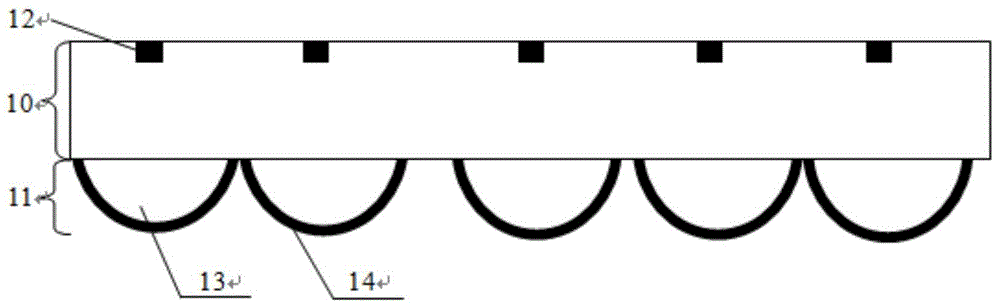
[0068] see Figure 1a , Schematic diagram of the structure of a 3D imaging optical film. The film has a three-layer structure: a transparent spacer layer 10 , a two-dimensional micro-reflective focusing unit array layer (or micro-reflective focusing unit array) 11 and a micro-text unit layer (micro-text unit) 12 . The two-dimensional micro-reflective focusing unit array layer 11 has a micro-focusing unit 13 and a micro-reflecting unit (or reflective layer) 14 .

[0069] The thickness of the transparent spacer layer 10 ranges from 10 microns to 5000 microns, preferably, the thickness of the transparent spacer layer is less than 1000 microns. The material of the transparent spacer layer can be PC, PVC, PET, PMMA, UV-sensitive curable glue, glass or BOPP, etc. Preferably, PET and UV-sensitive curable glue are selected.

[0070] The micro-focusing unit 13 and the micro-reflecting unit 14 focus the incident light from the second surface side of the transparent spacer layer on the ...

Embodiment 2

[0074] see Figure 4 , a schematic diagram of the visual effect of a 3D stereoscopic imaging film in the present invention. As described in the first embodiment of the present invention, the optical film can enlarge the micro-text 44 originally hidden in the micro-pattern layer so that the naked eye can directly distinguish it. The observer observes from the side of the second surface of the transparent spacer layer, and will see the only enlarged micro-text 45 suspended between the observer and the second surface of the transparent spacer layer. No matter when the imaging film is rotated along the horizontal axis 41 or the vertical axis 42, no other image of the second magnified microtext unit enters the viewing area. In addition, since the functioning micro-reflection focusing unit 43 is located on the second surface of the transparent spacer layer, it can be sealed with a protective material. When the first surface of the transparent spacer layer is covered by transparent...

Embodiment 3

[0076] The structure proposed by the present invention realizes the principle of floating 3D enlarged images as follows: Figure 5 shown. Set the radius of curvature R of the micro-reflection focusing unit, the focal length f, and the height di of the suspended image of the micro-graphic unit. then according to the attached Figure 5 Geometric relations in :

[0077] where x MLA Indicates the coordinate value of the micro-reflection focusing unit, x MPA Indicates the coordinate value of the microtext unit;

[0078] Get the height of the floating image:

[0079] d i = f - R 1 - x M P A x M L A + R . ...


PUM

PropertyMeasurementUnit
Diameteraaaaaaaaaa
Focal lengthaaaaaaaaaa
Thicknessaaaaaaaaaa

Abstract

The invention discloses a three-dimensional imaging optical thin film, which comprises a transparent spacing layer, a micro-reflective focusing unit array layer, and a micro-graphic unit array layer. The transparent spacing layer has two opposite surfaces. The micro-reflective focusing unit array layer is arranged on one surface of the transparent spacing layer and comprises a plurality of asymmetrically arranged micro-reflective focusing units. The micro-graphic unit array layer, opposite to the micro-reflective focusing unit array layer, is arranged on the other surface of the transparent spacing layer and comprises a plurality of micro-graphic units. The micro-reflective focusing unit array layer and the micro-graphic unit array layer are matched with each other, so that the three-dimensional imaging optical thin film can form one and only one suspended image suspended in the transparent spacing layer only when being viewed form the side of the micro-graphic units. The suspended image of the three-dimensional imaging optical thin film is a single-channel or multi-channel pattern. When the imaging thin film is inclined from side to side or inclined back and forth, no other amplified micro-graphic unit enters the viewing area. The thin film is unique in visual experience and can be clearly observed in the front perpendicular condition.

Description

technical field [0001] The invention relates to the technical field of optical films, in particular to a 3D imaging optical film. Background technique [0002] Various 3D imaging technologies are attracting more and more attention in the fields of information, display, medical treatment, and military affairs. The use of microlens technology to achieve three-dimensional imaging has great potential and prospects. It is developed from the integrated photography proposed by G. Lippman in 1908. A group of two-dimensional unit images with different perspective relations of the three-dimensional scene are recorded by a lens array and image acquisition, without special observation glasses and lighting, the three-dimensional image of the original scene can be directly observed in front of the display microlens array. With the development of microlens array manufacturing process and the popularization of high-resolution printing and image sensors, integrated imaging technology has a...

Claims


Application Information

Patent Timeline
IPC IPC(8): G02B3/00G02B27/22
Inventor 张健
Owner SHINE OPTOELECTRONICS KUNSHAN CO LTD
Why Eureka
Try Eureka