
P-band dual circularly polarized helical antenna

A helical antenna, dual circularly polarized technology, applied to antennas, resonant antennas, mid-position feeding between antenna endpoints, etc., can solve the problems of complex antenna structure and inability to dynamically switch circularly polarized modes, etc.

Active Publication Date: 2017-01-11
昆山亿趣信息技术研究院有限公司
View PDF6 Cites 10 Cited by
  • Summary
  • Abstract
  • Description
  • Claims
  • Application Information

AI Technical Summary

Problems solved by technology

Through the search of existing technical documents, it is found that the Chinese patent "Single Port Dual Frequency Dual Circular Polarization Antenna" (Application No. 2014107765979) relates to a dual frequency band dual circular polarization helical antenna. The helical arms of the same size realize dual-band dual circular polarization communication, in which the upper part of the antenna is composed of four small-sized helical arms, which radiate high-frequency right-handed circularly polarized electromagnetic waves; the lower part of the antenna is composed of four large-sized helical arms, Radiates low-frequency left-handed circularly polarized electromagnetic waves, but the antenna does not implement two circularly polarized radiation modes for electromagnetic waves in the same frequency band, and cannot implement dynamic switching of circularly polarized modes
Chinese patent "a conical four-arm sinusoidal antenna and its polarization control method" (application number 2015100676574) needs to add an additional feed network to generate excitation signals with equal amplitude and phase difference of 90 degrees, and the antenna structure is complex

Method used


Image

  • P-band dual circularly polarized helical antenna
  • P-band dual circularly polarized helical antenna
  • P-band dual circularly polarized helical antenna

Examples


Embodiment Construction

[0026] Below in conjunction with accompanying drawing and embodiment, the present invention will be further described: present embodiment is carried out under the premise of technical scheme of the present invention, has provided detailed implementation mode and concrete operation process, but protection scope of the present invention is not limited to the following the described embodiment.

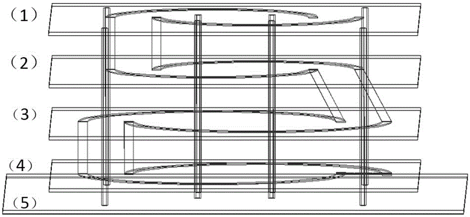
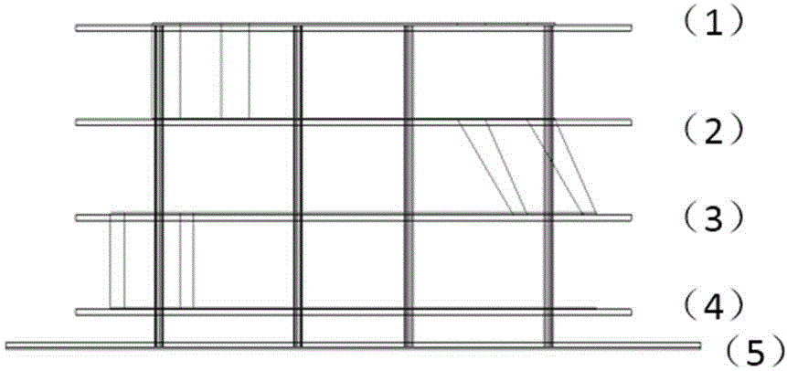
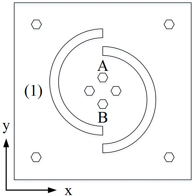
[0027] Such as Figure 1-6 As shown, the present invention provides a P-band dual circularly polarized helical antenna with a center frequency of 450Mhz and an overall size of 0.5m×0.5m×0.16m (length×width×height). This embodiment includes: the first layer of metal radiation Ring 1, the second layer of metal radiation ring 2, the third layer of metal radiation ring 3, the fourth layer of metal radiation ring (including radio frequency control circuit) 4, reflective floor layer 5. The initial size of the metal radiation ring described in this embodiment is calculated according to the emp...


PUM


Abstract

The invention belongs to the technical field of telecommunication and specifically relates to a P-band dual circularly polarized helical antenna. The antenna comprises, from upper to lower part, the first, second, third and fourth layer of metal radiation ring (including radio-frequency control circuit) and metal reflection layer; each layer of metal is engraved on the medium of epoxy glass cloth playing the role of supporting; each layer of metal radiation ring comprises two semicircular rings. The right semi-circular rings of metal of the first and the third layer are connected with the left semicircular rings of metal of the second and the fourth layer through a metal microstrip to form the right-hand circularly polarized helical antenna. The radio-frequency control circuit is located on the upper surface of the fourth layer of medium. The input end of the control circuit is connected with the SMA joint. The two output ends are respective connected with the left-hand circularly polarized helical antenna and the right-hand circularly polarized helical antenna. Signals are input from the SMA joint and the polarization mode of electromagnetic wave radiated by the antenna is selected by the radio-frequency control circuit.

Description

technical field [0001] The invention belongs to the technical field of antennas, and in particular relates to a P-band dual circularly polarized helical antenna. Background technique [0002] Due to its longer wavelength and strong penetrating ability, P-band has unique advantages in monitoring forest vegetation and ground surface. The Faraday rotation effect brought by the ionosphere will cause polarization mismatch in linearly polarized antennas, but circularly polarized antennas can well avoid this phenomenon. Most of the dual circularly polarized antenna structures in the prior art adopt dual-port or multi-port feed, that is, two circularly polarized antennas are integrated to work separately, and different circularly polarized modes are realized by inputting signals to different ports. [0003] A typical helical antenna is a traveling-wave antenna in the shape of a helical spring wound by a metal wire according to certain rules, and generally has good circular polariza...

Claims


Application Information

Patent Timeline
IPC IPC(8): H01Q9/27H01Q1/38H01Q15/24
CPCH01Q1/38H01Q9/27H01Q15/24
Inventor 张福恒杨国敏金亚秋
Owner 昆山亿趣信息技术研究院有限公司
Learn More