
Simulation method and device for generation value of combustion characteristic of pulverized coal of power station boiler

A technology of boiler combustion and pulverized coal combustion, which is applied in the field of electric power and can solve the problems of unrealistic test benches and irregular characteristic measurements.

Inactive Publication Date: 2017-01-18
ELECTRIC POWER RES INST OF GUANGDONG POWER GRID
View PDF4 Cites 10 Cited by
  • Summary
  • Abstract
  • Description
  • Claims
  • Application Information

AI Technical Summary

Problems solved by technology

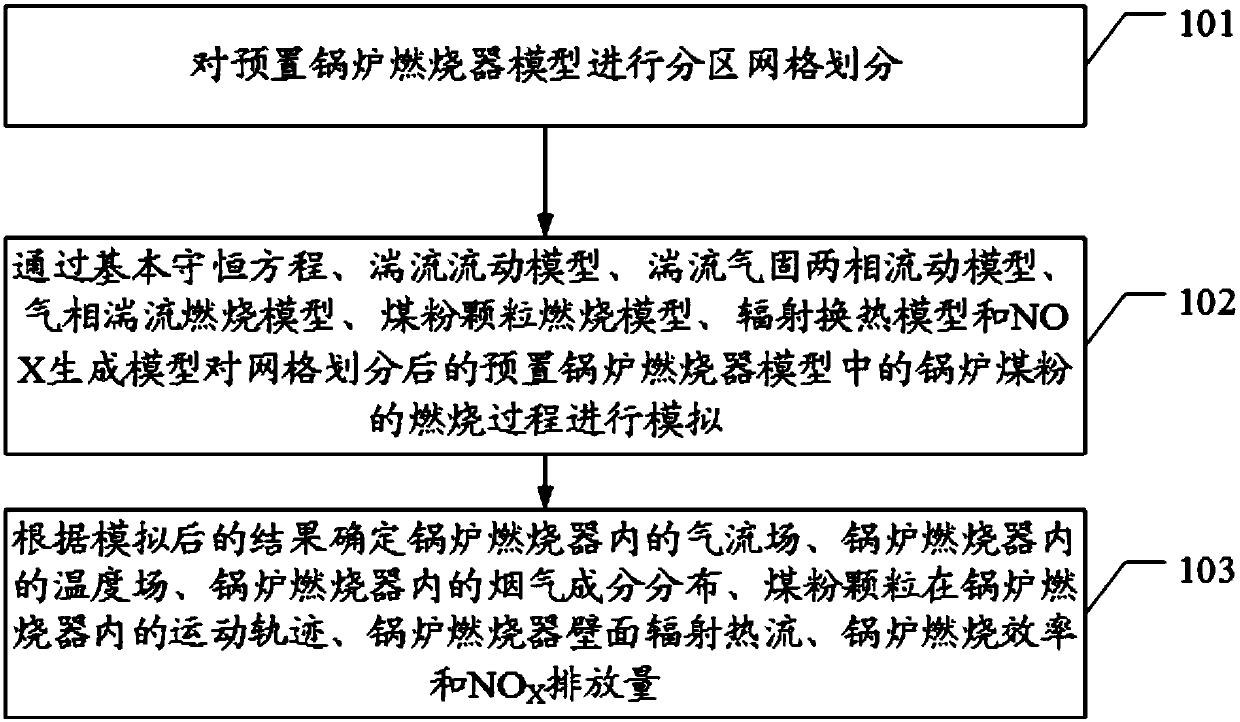
In this embodiment, the preset boiler burner model is partitioned and meshed; the basic conservation equation, turbulent flow model, turbulent gas-solid two-phase flow model, gas phase turbulent combustion model, pulverized coal particle combustion model, radiation heat transfer Model and NOX generation model simulate the combustion process of boiler pulverized coal in the preset boiler burner model after grid division; determine the airflow field in the boiler burner, the temperature field in the boiler burner, The distribution of flue gas components in the boiler burner, the movement trajectory of pulverized coal particles in the boiler burner, the radiant heat flow on the wall of the boiler burner, the combustion efficiency of the boiler and the NO X The emission rate solves the technical problem that it is impossible to measure the overall regular characteristics of combustion, flow and heat transfer in the furnace due to the increasing size of the furnace and the impracticality of manufacturing a full-scale model test bench.

Method used


Image

  • Simulation method and device for generation value of combustion characteristic of pulverized coal of power station boiler
  • Simulation method and device for generation value of combustion characteristic of pulverized coal of power station boiler
  • Simulation method and device for generation value of combustion characteristic of pulverized coal of power station boiler

Examples


Embodiment Construction

[0019] The embodiment of the present invention provides a method and device for simulating the combustion characteristics of power plant boiler pulverized coal to generate numerical values, which solves the problem that it is impractical to manufacture a full-scale model test bench due to the increasing size of the furnace. The technical problem of measuring the overall law characteristics of combustion, flow and heat transfer in the furnace.

[0020] CFD, software (Computational Fluid Dynamics), that is, computational fluid dynamics, is a branch of fluid mechanics, referred to as CFD. CFD is the product of the combination of modern fluid mechanics, numerical mathematics and computer science, and is a fringe science with strong vitality. It uses computer as a tool and applies various discrete mathematical methods to conduct numerical experiments, computer simulations and analytical research on various problems in fluid mechanics to solve various practical problems.

[0021] I...


PUM


Abstract

The invention discloses a simulation method and a simulation device for a generation value of a combustion characteristic of pulverized coal of a power station boiler, and solves the technical problem that the whole rule characteristics of combustion, flowing and heat transfer in the boiler cannot be measured due to the fact that a conventional hearth cannot be used for manufacturing a test bed of a full-size model as the size of the hearth is larger and larger. The method comprises the following steps: simulating a combustion process of the pulverized coal of the boiler in a preset boiler combustor model subjected to gridding division through a basic conservation equation, a turbulent flow model, a turbulent gas-solid two phase flow model, a gas phase turbulent combustion model, a pulverized coal particle combustion model, a radiation heat exchange model and an NOX generation model; determining a gas flow field in a boiler combustor, a temperature field in the boiler combustor, flue gas component distribution in the boiler combustor, a moving trace of pulverized coal particles in the boiler combustor, radiation heat flow on the wall surface of the boiler combustor, the boiler combustion efficiency and an NOX discharge amount according to a simulation result.

Description

technical field [0001] The invention relates to the field of electric power technology, in particular to a method and device for simulating numerical values ​​generated by pulverized coal combustion characteristics of power plant boilers. Background technique [0002] Pulverized coal combustion in power plant boilers is a complex three-dimensional process of turbulent flow, heat transfer and combustion. Due to the complexity of the process and the variability of coal-fired boiler fuel, so far, there is a lack of mature theory and experience in the design and operation of boilers, and cold and hot tests are often required to determine the operating and design parameters, because the test is intuitive, Reliability and other advantages can be directly used to guide the design, production and manufacture of boiler products. However, at present, my country's thermal power plants have developed towards high parameters and large capacity, and the size of the furnace is getting lar...

Claims


Application Information

Patent Timeline
IPC IPC(8): G06F17/50
CPCG06F30/23
Inventor 李德波许凯钟俊冯永新周杰联曾庭华廖永进湛志钢刘亚明殷立宝余岳溪
Owner ELECTRIC POWER RES INST OF GUANGDONG POWER GRID
Learn More